Standardized Protection Measures for Split Case Centrifugal Pumps During Extended Shutdowns
When a split case centrifugal pump remains out of service for an extended period due to equipment idling, suspended operating conditions, or seasonal shutdowns, failure to implement proper shutdown protection measures can easily lead to internal corrosion, bearing seizure, seal deterioration, frozen or cracked piping, impeller scaling, and other problems. These issues can significantly shorten the service life of the equipment and may also cause excessive vibration, leakage, pump seizure, and other operational risks when the pump is restarted, substantially increasing maintenance costs and the risk of unplanned downtime.
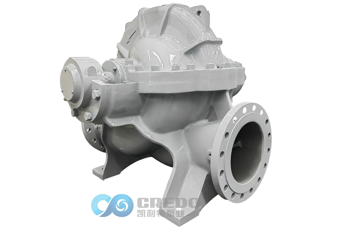
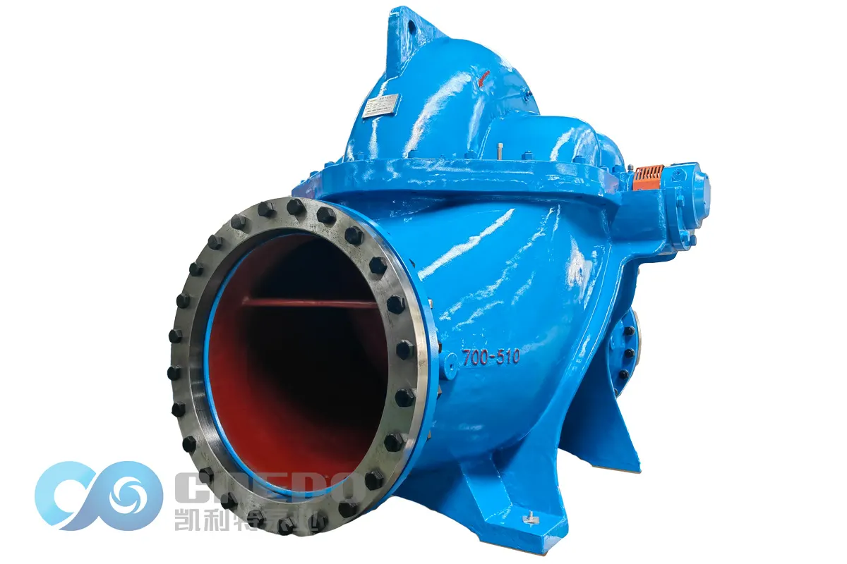
Based on the structural characteristics of split case centrifugal pumps and standard industry maintenance practices, this article systematically explains standardized protection measures for extended shutdown periods. The objective is to maintain the equipment in good condition while it is out of service and ensure smooth and reliable recommissioning whenever required.
1. Pre-Shutdown Cleaning and Draining
Proper preparation before shutdown is the foundation of effective protection. It helps prevent corrosion, scaling, and freeze damage caused by residual process fluid.
1.1 Standard Shutdown Procedure
The correct shutdown sequence is:
Gradually close the discharge valve → disconnect the motor power supply and wait until the pump comes to a complete stop → close the pressure gauge and vacuum gauge isolating valves → close the suction valve → open the drain plug at the bottom of the pump casing to completely drain the pump.
Do not shut down the pump while it remains pressurized, as this may cause pressure surges or water hammer that can damage critical internal components.
1.2 Complete Draining and Flushing
After shutdown, all residual liquid must be completely drained from the pump and associated piping. Open the drain plug at the bottom of the pump casing and remove all accumulated water, contaminants, and process-fluid residues from the pump chamber, flow passages, and seal chamber.
If the pump has handled wastewater or acidic or alkaline corrosive liquids, thoroughly flush the internal surfaces of the pump casing, impeller, shaft, and other critical components with clean water. All residual contaminants must be removed to prevent corrosive substances from remaining on metal surfaces and causing long-term oxidation and corrosion.
1.3 Drying
After draining and cleaning, allow all components to dry thoroughly and ensure that no standing water or residual moisture remains inside the pump.
Where necessary, use compressed air to blow dry low points and other areas where moisture may collect. Accessible internal surfaces may also be wiped with a clean, dry cloth and then allowed to air-dry in a well-ventilated environment.
2. Rust and Corrosion Protection for Critical Components
During extended shutdown periods, metal components of a split case centrifugal pump can corrode much more rapidly in humid environments than during normal operation.
During operation, the movement of the pumped fluid and the heat generated by bearing operation help keep component surfaces relatively dry, while lubricating oil films continuously protect metal surfaces. After shutdown, these protective mechanisms are no longer present. Moisture in the air can condense on metal surfaces, significantly accelerating corrosion.
Therefore, critical precision components such as bearings, shafts, impellers, and mechanical seals require particular attention.
The following table summarizes the standardized rust and corrosion protection requirements for major components. Unless otherwise specified, these measures should be carried out once on the day the pump is taken out of service.
| Critical Component | Main Risk During Shutdown | Standardized Protection Measure | Frequency | Acceptance Criteria |
| Pump shaft and bearings | Corrosion during prolonged inactivity, lubricant hardening, slight shaft distortion, and seizure or abnormal noise during restart | After cleaning and drying, apply a uniform coating of suitable water-displacing rust preventive oil to the exposed metal surfaces. The coating should be even, without excessive thickness, running, or accumulation. | One-time treatment on the shutdown date; dry film thickness should be controlled within 15–30 μm | Complete oil-film coverage, with no excessive running, accumulation, or exposed metal surfaces |
| Impeller and internal pump casing surfaces | Scaling caused by residual liquid and oxidation or corrosion of metal surfaces, resulting in reduced flow and blocked passages | After pumping corrosive media, thoroughly flush with clean water. After complete drying, apply rust protection to all relevant surfaces and seal the pump suction and discharge openings to isolate the interior from the atmosphere. | One-time treatment on the shutdown date | No standing water or residual contaminants; suction and discharge openings securely sealed |
| Mechanical seals and packing seals | Drying, aging, sticking, cracking, seal failure, and leakage during restart | Apply a thin, even layer of suitable lubricating and rust-preventive grease to the relevant seal contact areas, protecting them from air and dust and preventing dry deterioration. | One-time treatment on the shutdown date | No cracking or sticking; lubricant applied evenly in a thin layer |
| Flanges, bolts, and coupling | Corrosion of exposed metal, seized bolts, and corrosion or deformation of the coupling | Apply rust preventive oil to all exposed metal surfaces. Install protective covers on flanges and provide dust protection for exposed components. | One-time treatment on the shutdown date | Complete protective coating, securely fastened covers, and no visible corrosion |
Protection Precautions
Rust preventive oil should uniformly cover the metal surface without excessive runoff or accumulation. Do not apply excessively thick layers, as hardened deposits may affect rotational accuracy.
Do not apply excessive grease, as it can attract contaminants and affect sealing surface performance and sealing accuracy.
After protection measures have been completed in humid environments, maintain adequate ventilation and drying conditions to prevent moisture condensation on the pump.
3. Freeze Protection and Insulation in Low-Temperature Environments
Low-temperature seasons are high-risk periods for freeze-related damage during shutdown. Freeze protection should be implemented using the following three-level strategy.
3.1 Complete Draining — Preferred Method
As described in Section 1, ensure that no water remains inside the pump casing, at low points in the piping, inside valve cavities, at drain connections, or in any other areas where liquid may collect.
Particular attention should be given to low points and dead legs, such as U-shaped piping sections and instrument pressure-sensing lines.
3.2 Filling Non-Drainable Areas with Antifreeze — Supplemental Measure
For areas that cannot be completely drained, such as seal chambers and instrument tubing, fill the remaining spaces with an industrial antifreeze compatible with the pump materials.
An ethylene glycol-based antifreeze may be used, with the concentration selected according to the lowest expected local ambient temperature. Formulations containing chloride ions must not be used.
The antifreeze volume should be sufficient to protect all internal metal surfaces within areas that cannot be completely drained.
3.3 Insulation and Heat Tracing — Auxiliary Measures
Wrap pump suction and discharge piping, valves, drain connections, and other freeze-prone areas with thermal insulation having a thickness of at least 50 mm, or use suitable removable insulation jackets.
For outdoor equipment or pumps installed in unheated pump rooms, provide an enclosed temporary thermal shelter.
For equipment operating under critical conditions, install self-regulating electric heat tracing to maintain the equipment surface temperature at approximately 5–10°C. A temperature controller and residual-current protection must be provided. Adequate clearance must also be maintained to ensure proper motor cooling and prevent overheating.
3.4 Environmental Monitoring
During the shutdown period, regularly monitor the temperature in the pump room.
When the ambient temperature is expected to remain within 5°C of the freezing point of the pumped liquid for an extended period—typically when the ambient temperature is 5°C or below—the above freeze protection measures should be fully implemented.
Even when the pump itself has been completely drained, piping insulation should still be maintained when the ambient temperature falls to 0°C or below.
Never leave equipment containing water idle throughout the winter. In cold and humid environments, if complete draining is not possible, the remaining liquid must be replaced or protected with suitable antifreeze, together with adequate insulation, to prevent the pump casing and piping from freezing and cracking.
4. Periodic Inspection and Maintenance During Shutdown
Equipment preservation does not mean simply leaving the pump unattended. Periodic maintenance is essential for preventing seizure, lubricant hardening, and localized corrosion.
The following inspection requirements are recommended:
| Inspection Interval | Key Inspection Items | Acceptance Criteria | Corrective Action |
| Once per month | Manually rotate the pump shaft and inspect transmission components | Shaft rotates freely without binding, abnormal resistance, or unusual friction noise; coupling alignment remains normal | If binding or abnormal noise occurs, investigate immediately, replenish lubricants or rust preventive products as required, and rotate the shaft repeatedly until smooth operation is restored |
| Once per month | Inspect rust preventive coatings, protective covers, and insulation | Rust preventive coating remains intact, with coating loss not exceeding 10%; covers are securely sealed; insulation is undamaged | If coating loss exceeds 10%, repair the coating within 24 hours; retighten loose covers; repair damaged insulation immediately |
| Once per month | Inspect the pump room environment and equipment dryness | Area is dry and well ventilated, with no standing water or excessive dust; no moisture condensation is present on the pump | Improve ventilation, remove accumulated water and dust, and add dehumidification measures in humid environments, such as dehumidifiers or moisture-absorbing materials |
Additional Requirements for Manual Shaft Rotation
Manually rotate the shaft by at least two complete revolutions (720°) every month.
The shaft position should be offset from the previous inspection position. A rotation offset of approximately 120°–180° is recommended for each inspection. This helps ensure that bearing raceways and sealing surfaces are evenly exposed to the protective lubricant and prevents the same position from remaining under load for extended periods, which could cause localized deformation.
Regularly inspect the pump room environment and maintain dry, well-ventilated, and clean conditions free from standing water and excessive dust. Prevent moisture-related deterioration, mold growth, and electrochemical corrosion.
At the same time, check the condition of protective covers, insulation, and rust preventive coatings. Any coating damage, loose covers, or damaged insulation should be repaired promptly as part of routine preventive maintenance.
5. Equipment Preservation and Identification Management
After all protection measures have been completed, provide overall dust protection for the equipment.
Use a waterproof and dustproof protective cover to completely enclose the pump and motor, protecting them from dust and moisture. Attach an out-of-service preservation tag indicating:
Shutdown date
List of protection measures completed
Date of the next scheduled inspection
Name of the responsible person
A corresponding equipment preservation record should also be maintained to ensure standardized management and full traceability of all inspections, repairs, and corrective actions.
6. Pre-Startup Inspection Before Returning the Pump to Service
Before the equipment is returned to service, complete the following checks and confirm that all requirements have been met before performing a trial run:
Step 1: Remove Preservation Measures
Remove all protective materials and preservation devices, including dust covers, suction and discharge opening covers, preservation tags, and other temporary shutdown protection items.
Step 2: Remove Protective Oils and Grease
Thoroughly remove rust preventive oil and grease applied to the pump shaft, bearings, seal areas, and other relevant components to prevent contamination of the pumped medium or adverse effects on sealing performance after startup.
Step 3: Inspect Component Condition
Check the mechanical seals, bearings, coupling, bolted connections, and other components for corrosion, deformation, looseness, or other damage.
Step 4: Verify Free Rotation by Manual Turning
With the pump unloaded, manually rotate the shaft through 2–3 complete revolutions and confirm that it rotates freely without binding or abnormal friction noise.
Step 5: Restore the Piping System
Confirm that the suction and discharge valves are in their correct operating positions, instrument isolating valves are open as required, and all drain plugs are securely tightened.
Step 6: Perform a Bump Test
For the initial startup, perform a bump test by briefly energizing and immediately de-energizing the motor. Confirm the correct motor rotation direction and verify that no abnormal vibration occurs before proceeding with continuous operation.
Conclusion
The key principles for protecting a split case centrifugal pump during an extended shutdown can be summarized as:
Drain and control moisture → prevent corrosion and freezing → perform periodic maintenance → preserve and manage the equipment systematically.
The corresponding measures are summarized below:
| Protection Principle | Related Section | Key Actions |
| Drain and control moisture | Section 1: Pre-Shutdown Cleaning and Draining | Standard shutdown → complete draining and flushing → thorough drying → sealing and isolation |
| Prevent corrosion and freezing | Section 2: Critical Component Protection + Section 3: Low-Temperature Freeze Protection | Apply rust protection to critical components + use the three-level strategy of draining, antifreeze, insulation, and heat tracing as required |
| Perform periodic maintenance | Section 4: Periodic Maintenance During Shutdown | Monthly shaft rotation + inspection of protective coatings and insulation + environmental monitoring; close corrective actions within 24 hours when required |
| Standardized preservation | Section 5: Preservation and Identification + Section 6: Pre-Startup Inspection | Dust protection → identification and maintenance records → six-step verification before restart |
Strict implementation of these protection measures can effectively prevent common equipment failures during extended shutdown periods, maintain mechanical condition and operating accuracy, extend equipment service life, and ensure efficient, safe, and reliable operation after recommissioning. Proper shutdown protection also helps reduce maintenance costs and unnecessary equipment replacement.
Appendix: Quick Reference Table for Key Parameters
| Parameter | Standard Requirement |
| Rust preventive oil | Suitable water-displacing rust preventive oil for temporary corrosion protection |
| Rust preventive oil film thickness | Dry film thickness of 15–30 μm, uniformly applied without excessive accumulation |
| Shaft rotation requirement | At least 2 complete revolutions per month, with the shaft position offset by 120°–180° from the previous position |
| Insulation thickness | ≥50 mm |
| Electric heat tracing temperature | Maintain approximately 5–10°C, with a temperature controller and residual-current protection |
| Antifreeze selection | Ethylene glycol-based, chloride-free, with concentration selected according to the lowest expected temperature |
| Coating repair time | Reapply within 24 hours when coating loss exceeds 10% |
| Manual rotation before restart | Rotate the shaft unloaded for 2–3 complete revolutions and confirm there is no binding |
Related Posts