Vertical Lineshaft Turbine Pump Vibration and Noise: Monitoring & Troubleshooting
Excessive vibration in a vertical lineshaft turbine pump can damage the guide bearings, shaft sleeves, and mechanical seals long before the impeller shows significant wear. Vertical turbine pumps such as VS1 and VS6 types have relatively slender shafts, multiple intermediate supports, and a motor mounted high above the discharge head, making the shaft system inherently more susceptible to vibration.
More importantly, many field inspections focus only on whether the pump is vibrating, while overlooking noise. In fact, abnormal noise can serve as an early warning of developing vibration problems. By the time vibration reaches the alarm threshold, wear may have already occurred.
This article addresses three key questions: Where does vibration come from? How should it be measured properly? And what should be done when vibration exceeds the allowable limit?
1. Why Are Vertical Lineshaft Turbine Pumps Particularly Susceptible to Vibration?
Three inherent factors tend to compound the problem:
High shaft flexibility:
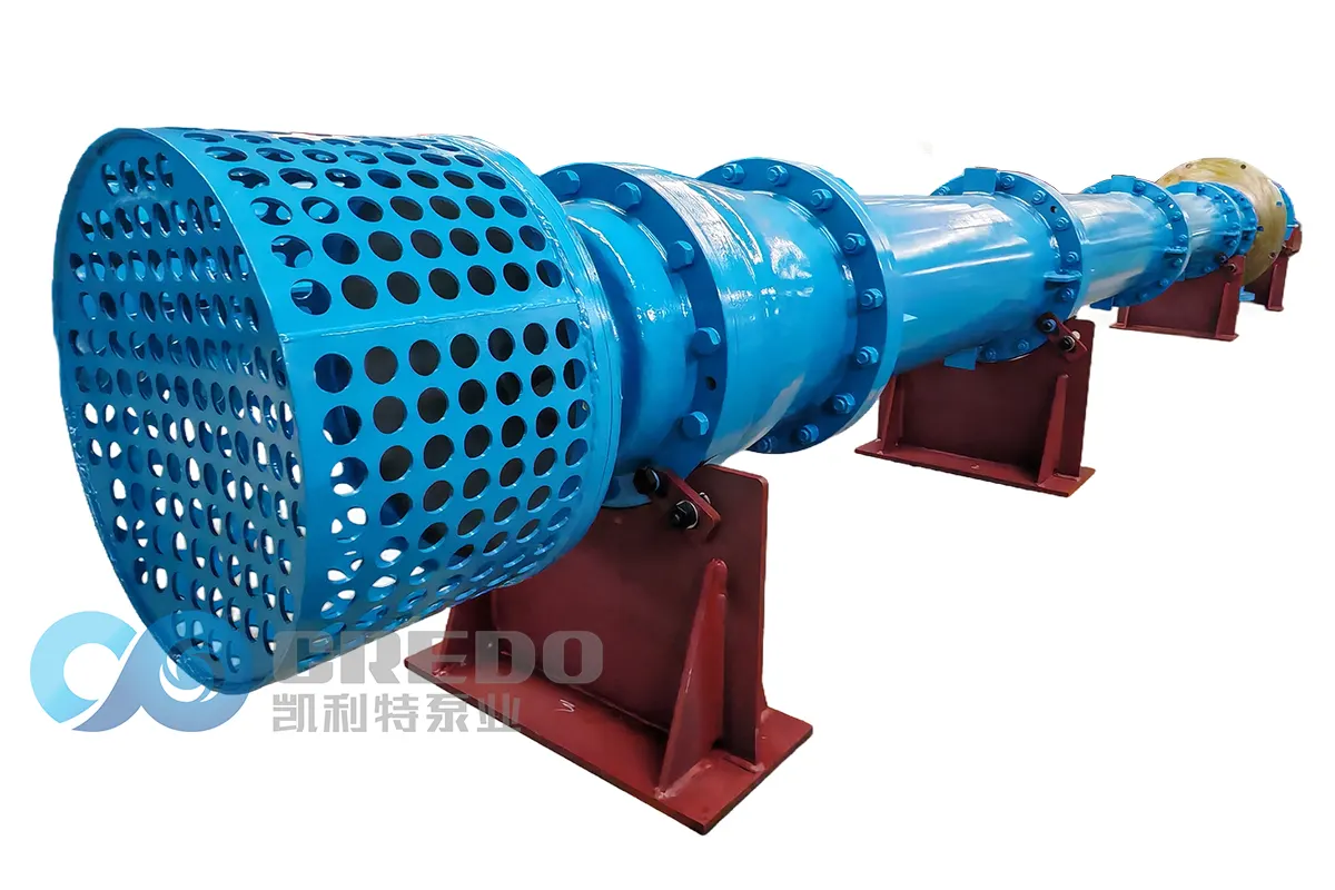
A lineshaft several meters or even more than ten meters long is supported at multiple points by intermediate guide bearings, which may use rubber, Thordon, graphite, or other bearing materials. If clearance increases at any one bearing, the shaft can begin to whirl.
Structural resonance:
The motor and discharge head form a cantilevered structure with its own natural frequency. When this frequency coincides with the operating speed frequency, vibration can be amplified several times. In engineering practice, a separation margin of at least ±10% is generally maintained between the operating frequency and the structural natural frequency.
Hydraulic excitation:
Operation away from the best efficiency point, cavitation, and rotor-to-stationary-component interaction between the impeller and diffuser or guide vanes can all introduce excitation into the rotating system.
These factors rarely occur independently. One of the most common field conditions is a combination of operation at an unfavorable flow rate and worn guide bearings. When the pump operates away from its preferred flow range, hydraulic radial forces become unbalanced, increasing the load on the guide bearings and accelerating bearing clearance growth. The increased clearance then further amplifies vibration, creating a positive feedback loop.
This is why many vertical lineshaft turbine pumps become progressively more unstable during service rather than failing suddenly.
2. How to Measure Vibration: Measurement Points, Parameters and Acceptance Criteria
Measurement points and parameters
Measurement points should be established at the thrust bearing housing and the motor top support, with measurements taken in the horizontal, vertical, and axial directions. The highest value should be used for evaluation.
Sensors should be rigidly stud-mounted whenever possible. Magnetic mounts and handheld measurements can attenuate high-frequency components and reduce measurement accuracy. See ISO 5348 for relevant guidance on accelerometer mounting.
The primary parameter should be RMS vibration velocity (mm/s) over a frequency range of 10–1000 Hz. For operating speeds below 600 r/min, peak-to-peak displacement should also be measured because vibration velocity is less sensitive to very low-frequency faults.
Use two criteria for vibration assessment
Vibration should be evaluated using both:
·Absolute vibration amplitude
·Change from the established baseline
Even when the measured value remains within the acceptable range, an increase of approximately 25% above the baseline should trigger an inspection.
The general evaluation framework can be based on the A/B/C/D zones specified in ISO 20816-1, with applicable limits referenced from ISO 20816-3 and the dedicated standard for rotodynamic pumps, ISO 20816-7. The measurement and analysis procedure should follow ISO 13373-1 and ISO 13373-2.
Distinguish between the two main industry criteria
For VS1/VS6 vertical turbine pump applications, ANSI/HI 9.6.4 specifies preferred operating region (POR) vibration limits of ≤3.3 mm/s for pumps below 200 kW and ≤4.3 mm/s for pumps rated at 200 kW or above. The allowable operating region (AOR) limits are 4.3 mm/s and 5.6 mm/s, respectively.
For vertical pumps used in petrochemical applications, API 610 specifies a POR vibration limit of 5 mm/s and an AOR limit of 6.5 mm/s, with additional limits applied to discrete frequency components.
The applicable standard should always be determined by the pump type, application, project specifications, and contractual requirements.
Measure noise using sound power level for meaningful comparisons
For standardized environmental measurements, ISO 3744 can be used with the enveloping measurement surface method. When the pump cannot be shut down or background noise interferes with the measurement, the ISO 9614 sound intensity method can be used.
For workplace noise exposure, ISO 11202 can be used to determine emission sound pressure levels at the operator’s position.
A measurement report should record the flow rate, rotational speed, and suction conditions at the time of measurement. Without this operating data, noise measurements are difficult to compare meaningfully.
3. Using Noise to Help Identify the Fault
Different faults tend to produce characteristic combinations of noise and vibration spectra.
·Low-frequency humming with a dominant 1× running-speed component: typically associated with rotor unbalance.
·A prominent 2× running-speed component accompanied by high axial vibration: often indicates misalignment.
·A strong blade-pass frequency (number of blades × running speed): may indicate uneven clearances or eccentricity between the impeller and stationary components.
·High-frequency broadband noise accompanied by a sound resembling gravel or sand being circulated: typically associated with cavitation.
·An electromagnetic hum at twice the electrical supply frequency: generally points to an electrical or motor-related source.
·Cavitation is one of the easiest faults to misdiagnose
Cavitation can sound like a damaged bearing, producing a characteristic rattling, crackling, or “gravel-like” noise. However, its frequency spectrum typically shows a broadband increase in high-frequency energy rather than a distinct discrete peak.
If the noise decreases significantly when the pump is brought back toward its preferred operating range, cavitation becomes a strong possibility. This provides a practical way to distinguish cavitation from mechanical faults without immediately shutting down the pump.
4. What to Do When Vibration Exceeds the Limit
The objective should not simply be to reduce the vibration reading. The underlying cause must be identified and corrected.
Dynamic balancing of the rotor
Balance rotating components in accordance with ISO 21940-11, typically to G2.5 balance quality grade. For more demanding applications, G1 may be specified.
For vertical lineshaft turbine pumps, the motor rotor should not be overlooked. In some cases, motor rotor balance has a greater influence on overall vibration than pump rotor balance, particularly when measurements are taken at the motor top support.
Check shaft alignment and straightness
Check the concentricity and alignment between the head shaft and motor shaft.
For hollow-shaft motors, verify the condition and fit of the steady bushing. For solid-shaft motors, use a precision coupling and verify coupling alignment carefully.
Avoid structural resonance
Perform a natural-frequency analysis of the discharge head and motor support structure.
If necessary, add structural supports or stiffeners, or modify the baseplate stiffness to shift the natural frequency away from the operating frequency.
This step is often overlooked, but it can be one of the most effective corrective measures for pumps with motors mounted high above the foundation.
Return the pump to an efficient operating range and verify NPSH
Bring the flow rate back toward the pump’s preferred operating range, typically 70%–120% of the best efficiency point (BEP), and verify that the available NPSH is adequate.
Replace intermediate guide bearings and shaft sleeves
Inspect the guide bearing clearance and the lubrication water passages.
If the clearance exceeds the specified tolerance, replace the bearing rather than relying solely on flow adjustment to suppress vibration.
Check for foundation voids and piping strain
Inspect for:
·Voids or inadequate contact beneath the secondary grout
·Forced-fit or excessive strain in the discharge piping
·Incorrect or insufficient pipe supports
·Improper installation or restraint of expansion joints
·A significant portion of pump vibration problems can originate outside the pump itself.
·Acoustic enclosures and vibration-isolation foundations: last-resort measures
These measures should only be considered after the underlying mechanical, hydraulic, structural, and installation-related causes have been eliminated and the pump still fails to meet applicable workplace noise limits.
Conclusion
Vibration and noise are not two independent problems. They are two different signals from the same machine: vibration is often the result, while abnormal noise can be an early warning sign.
The most effective troubleshooting approach is to establish accurate baseline measurements using the ISO 20816 series, document operating and measurement conditions in accordance with ISO 13373, and then investigate the system step by step—from hydraulic conditions to mechanical components, structural behavior, and foundation/piping conditions.
Correct the root cause first; only then should acoustic enclosures or vibration-isolation measures be considered.
The simplest and most effective practice is to establish fixed measurement points and monitor them monthly, using the same locations, directions, and operating conditions whenever possible. Let the equipment “tell you” what is happening.
In many cases, developing guide bearing wear, seal deterioration, and even shaft failures can be detected and addressed before an unplanned shutdown occurs.
FAQ
Q: How often should vibration be measured?
A: Critical units should be monitored continuously when online condition monitoring is available. For general-duty units, monthly measurements are recommended, with additional measurements after significant changes in operating conditions.
Q: Which vibration limit should be used for a new pump during acceptance testing?
A: Factory testing should follow the applicable ANSI/HI 9.6.4 factory acceptance criteria. Field acceptance should use the applicable site acceptance criteria. For petrochemical projects, API 610 should be followed when specified by the contract or project requirements.
Q: What if vibration is within the acceptable range but the pump is unusually noisy?
A: The most likely causes include cavitation, two-phase flow, or excessive valve throttling. First check the operating point and suction conditions rather than using an acoustic enclosure to mask the underlying problem.
Related Posts