Horizontal Split Case Pump Lifting, Positioning and Alignment: A Standardized Installation Process Based on ISO Standards
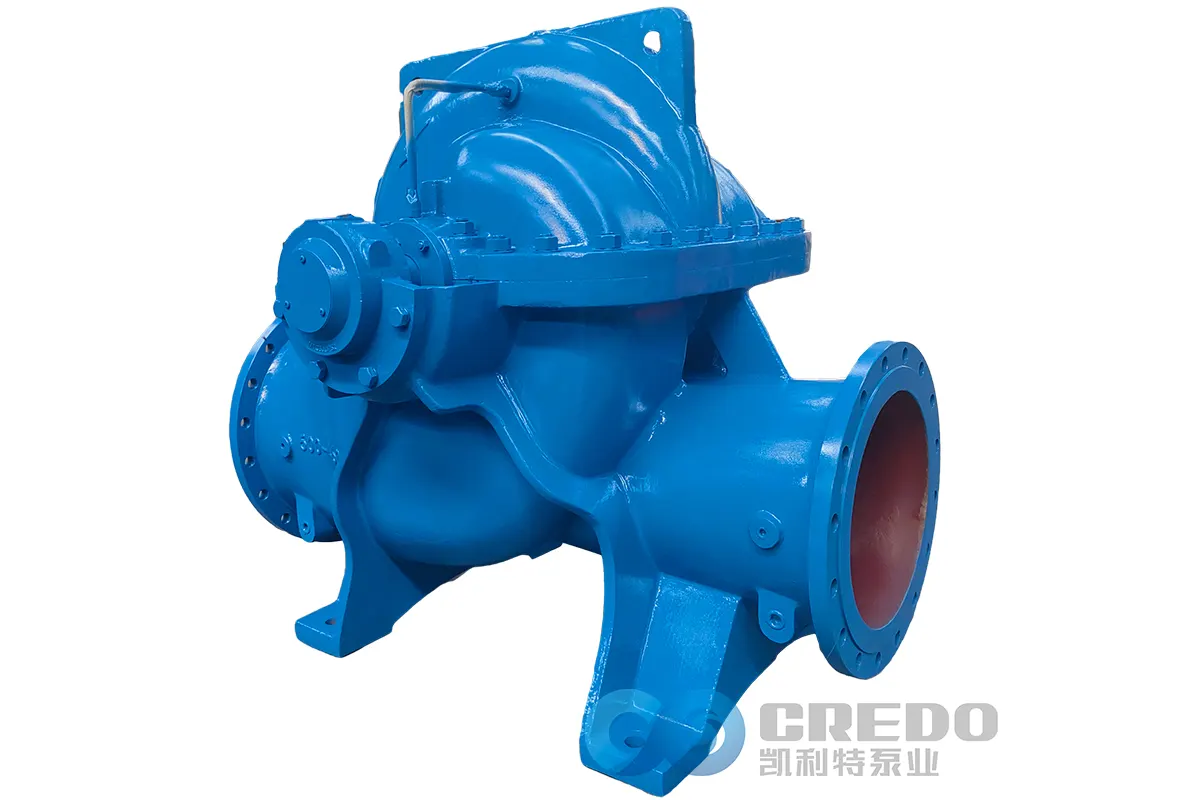
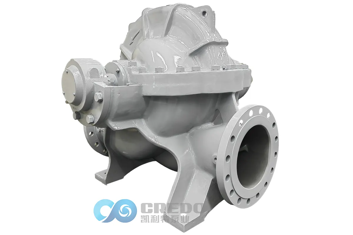
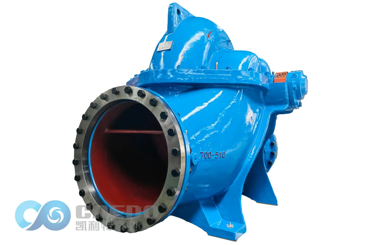
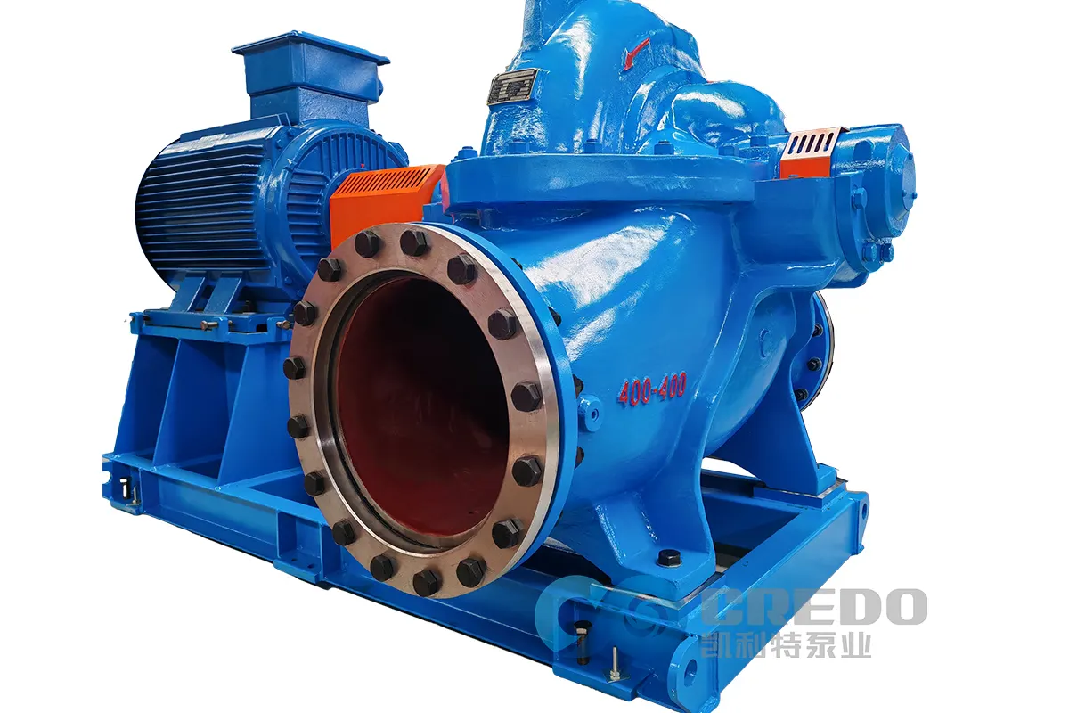
The installation quality of a horizontal split case pump (horizontal split-case, double-suction centrifugal pump, BB1/BB2 type under ISO 13709) is determined by three critical installation stages: lifting, positioning, and alignment. The key controls for each stage are: controlling loads and preventing deformation during lifting; controlling elevation and level during positioning; and controlling shaft alignment and piping loads during final alignment.
This article provides an executable installation procedure, quantitative control criteria, and acceptance methods based on the ISO standards framework. It applies to the installation of horizontal split case pumps supplied either as complete units or in separate components for industrial water supply and drainage, municipal water supply, and water conservancy projects.
I. Three Typical Failure Modes: Why Each Installation Stage Matters
| Failure Mode | Direct Cause | Installation Stage Involved |
| Excessive vibration and premature bearing failure | Coupling misalignment, soft foot, and external piping loads | Alignment and piping connection |
| Mechanical seal leakage and shaft sleeve wear | Pump casing deformation, shaft misalignment, and piping strain | Lifting, positioning, and piping |
| Base looseness and loss of final leveling accuracy | Improper shim arrangement, inadequate grouting, and insufficient curing | Positioning and grouting |
Field experience shows that the majority of horizontal split case pump failures after commissioning are not caused by manufacturing defects, but by skipped or improperly executed installation steps. The following sections therefore follow a closed-loop sequence:
Preparation → Lifting → Positioning → Grouting → Alignment → Piping → Acceptance
II. Installation Preparation and Foundation Inspection
1. Foundation Inspection
Confirm the concrete foundation strength against the design documents. In general, installation should not begin until the concrete has reached at least 75% of its specified design strength. Strength testing and evaluation should be carried out in accordance with the applicable ISO 1920 series test methods.
Recheck the foundation centerlines, elevation, and anchor-bolt hole positions. As a general reference, positional deviations should be controlled within ±5 mm, with elevation deviations within ±5 mm.
Chip and roughen the foundation surface and remove laitance, oil, and other contaminants. The areas where shims will be installed must be ground level. The contact area should be at least 50%; use a 0.05 mm feeler gauge to check that the insertion depth does not exceed one-third of the shim length.
2. Unpacking Inspection and Pre-Installation Checks
Verify the model and nameplate data of the pump, motor, and common baseplate, and check all supplied accessories and special tools.
Check that the rotor turns freely and verify the rotor balance grade, generally not lower than ISO 1940-1 Grade G2.5.
Inspect the mechanical seal and seal-flush piping. The flushing arrangement should comply with ISO 21049. Confirm that there is no damage caused during transportation.
Confirm the coupling type and its allowable compensation capacity. These values will be used as the basis for determining the final alignment tolerances.
III. Lifting: Control the Loads and Prevent Structural Deformation
The basic principles of lifting are controlled loading, designated lifting points, and zero impact.
Lifting Equipment and Lifting Points
The crane rated capacity should be checked against at least 1.2 times the total weight of the pump unit. Slings, shackles, and spreader beams must have valid identification and certification. Damaged or overloaded lifting equipment must never be used.
The pump must be lifted using the designated lifting lugs/lifting points on the pump casing or the sling positions specified by the manufacturer.
Never lift the pump by wrapping slings around the pump shaft, coupling, suction or discharge flanges, mechanical seal, or instrument connections.
The angle between the sling and the vertical should preferably be no greater than 60° and must not exceed 90°. As the angle increases, sling tension increases, so the lifting arrangement must be checked accordingly.
Protection and Handling
Fit rubber sleeves, edge protectors, or equivalent protection wherever slings contact sharp edges of the pump casing to protect the coating and machined surfaces.
Keep the pump level during lifting. Raise, lower, and move the pump smoothly and at a controlled speed. Avoid sudden stops, abrupt changes in direction, or side loading.
Use tag lines throughout the lifting operation to prevent the pump from striking the foundation or supporting structures.
For split-assembly installation, such as when the pump casing is opened on site, the rotor must be lifted with dedicated lifting equipment and kept level. Never lift the rotor by the impeller or shaft sleeve. After opening the casing, the horizontal split-case joint faces must be specially protected.
IV. Positioning, Leveling and Initial Alignment: Shims Are Critical
1. Shim Arrangement
Shim packs should be positioned on both sides of the anchor bolts and beneath the load-bearing ribs or structural members of the baseplate. The recommended spacing between shim packs is 500–1000 mm.
Each shim pack should generally contain no more than five pieces. Tapered shims used as a matched pair are counted as two pieces.
The shims should extend 10–30 mm beyond the outer edge of the baseplate, while the portion extending beneath the baseplate should reach beyond the centerline of the anchor bolt.
The overlap between tapered shims should be at least three-quarters of their total length.
After leveling is completed and accepted, the shim packs should be tack-welded or otherwise secured as specified by the installation procedure.
Note: The number of foundation shims and the thin stainless-steel adjustment shims used for motor alignment are two different concepts and must not be confused. Motor alignment shims are generally limited to no more than three pieces.
2. Positioning and Leveling
Lower the pump unit smoothly onto the foundation, align it with the foundation centerlines and installation reference lines, and leave sufficient adjustment allowance around the anchor bolts.
As a general reference, the centerline position deviation should be ≤±5 mm and the installation elevation deviation should be ≤±5 mm.
Use a 0.02 mm/m precision machinist’s level or precision spirit level to check level. The measurement points should include:
Horizontal split joint face of the pump casing — measure both longitudinal and transverse level.
Bearing housing split face / pump shaft journal — verify the level of the pump shaft.
Do not use the suction or discharge flange faces to measure horizontal level. These are vertical faces and indicate vertical alignment rather than horizontal level.
Control values: For split-assembly installation, longitudinal levelness should be ≤0.05/1000. For complete-unit installation, longitudinal levelness should be ≤0.1/1000 and transverse levelness ≤0.2/1000, unless otherwise specified by the manufacturer.
3. Common Baseplate vs. Split Baseplate
Complete unit with a common baseplate: Alignment is normally completed at the factory. On site, the primary task is verification. Adjustment is only required if transportation, lifting, or grouting has caused the alignment to fall outside the specified tolerance.
Split baseplate / separate foundation arrangement: The pump is positioned and leveled first, followed by motor installation. The complete field alignment procedure must then be carried out.
V. Grouting and Curing: The Often-Skipped Steps That Can Cause the Most Problems
This is one of the most frequently overlooked stages, yet it directly determines whether the final alignment can be maintained.
Primary grouting:
Grout the anchor-bolt pockets after removing debris and wetting the holes. Use the specified grout material and ensure complete filling without voids.
Secondary grouting:
Fill the gap between the baseplate and foundation. The grout layer is generally 30–70 mm thick.
Grouting should be continuous, dense, and completed in one operation. No voids should remain beneath or inside the baseplate.
Anchor bolts should be selected according to the property classes specified in ISO 898-1. Tightening torque should follow the design documents, with bolts tightened symmetrically and in stages.
The curing period should generally be at least 7 days. Precision alignment should not begin until the grout has reached at least 75% of its specified design strength.
Core principle: Final precision alignment must be carried out after secondary grouting and curing are complete. The alignment must then be rechecked after the piping has been connected.
Grout shrinkage and anchor-bolt tightening can cause equipment movement. Performing final alignment too early effectively means doing the job twice.
VI. Precision Coupling Alignment: Eliminate False Readings Before Taking Measurements
1. Two Essential Pre-Alignment Checks
1-1. Soft Foot Check
Poor contact between the equipment feet and the baseplate can deform the equipment when the anchor bolts are tightened, making all subsequent dial-indicator readings unreliable.
To check soft foot, position a dial indicator near the equipment foot and loosen the anchor bolts one at a time while measuring the amount of lift. As a general reference, the lift should be ≤0.05 mm.
If the value exceeds the limit, correct it using full-piece stainless-steel shims. Do not use multiple layers of thin shim stock.
1-2. Check Runout of the Coupling Half
Rotate the shaft and measure the radial and face runout of the coupling half. As a general reference, runout should be ≤0.02–0.03 mm.
Confirm that there is no excessive wobble or face distortion before using the coupling half as the reference for alignment measurements.
2. Rough and Precision Alignment
Coupling gap: Set the gap according to the coupling manufacturer’s specified value for the particular coupling model. The required axial movement and thermal expansion must also be taken into account. Do not use a universal 3–5 mm value.
Rough alignment: Use a straightedge and feeler gauge to eliminate obvious parallel and angular misalignment.
Precision alignment: A laser alignment system is preferred. Enter the correct equipment dimensions and ensure that the brackets are securely mounted.
Where laser alignment is not available, the three-dial-indicator method can be used: one indicator measures radial displacement, while two indicators are positioned 180° apart on the face to obtain averaged readings and minimize the effect of axial movement during rotation.
Take readings at 0°, 90°, 180°, and 270°. The readings should close properly. The indicator bracket must be sufficiently rigid, bracket sag should be checked before measurement, and the indicator stem should be perpendicular to the measured surface.
3. Alignment Acceptance Criteria
Alignment should be controlled according to ISO 14691 and the allowable compensation specified by the coupling manufacturer. The following two independent parameters should be evaluated separately:
| Parameter | Description | Common Reference Value (Manufacturer’s Limits Prevail) |
| Radial offset | Parallel offset between the centerlines of the two shafts | Generally ≤0.05 mm |
| Angular misalignment | Angle between the two shaft centerlines, represented by face readings | Generally ≤0.05 mm per 100 mm of flange diameter |
Note: Coupling alignment should not be evaluated using “concentricity” as a single parameter. “Concentricity” is a geometrical tolerance defined in ISO 1101. In practical shaft alignment, radial offset and angular misalignment are two independent parameters that must be controlled separately.
4. Cold Alignment Compensation and Rechecking
Calculate the required cold alignment offset based on the operating temperature of the pumped medium and the thermal expansion of the pump and motor. In hot operating conditions, the motor centerline will typically need to be positioned higher to compensate for thermal growth, ensuring that both cold and operating conditions remain within the specified alignment tolerance.
After piping installation and completion of grout curing, the alignment must be checked again. Perform another final verification before commissioning.
VII. Piping Connection and Control of External Loads
External piping forces are a major cause of excessive vibration during operation and can have a greater impact than alignment errors themselves.
Piping must be independently supported. Pump flanges must not carry the weight of the piping or thermal expansion forces.
Match flange dimensions and pressure ratings in accordance with ISO 7005. With the piping in a free, unstressed condition, check flange parallelism. As a general reference, the deviation should be ≤0.1–0.2 mm, and the bolts should pass freely through the holes.
Dial-indicator monitoring: Mount a dial indicator at the coupling and monitor displacement while tightening the piping flange bolts symmetrically. The displacement measured at the coupling should be ≤0.05 mm. If the value exceeds the limit, the piping must be realigned. Never force the piping into position.
Connect and flush the mechanical seal flush and cooling-water piping in accordance with the applicable ISO 21049 flushing requirements. Confirm that the piping is clean before introducing the flush water.
VIII. Commissioning and Acceptance: Close the Loop with Quantitative Criteria
Before commissioning, check the following:
Rotate the shaft manually to confirm smooth rotation without binding or abnormal noise.
Perform a motor-only test to confirm the correct direction of rotation.
Fill or replenish the lubricant according to the specified oil or grease level.
Install the coupling guard in accordance with ISO 14120.
Ensure that the work area has been completely cleaned.
After startup, evaluate the pump in accordance with ISO 9906 and ISO 10816-7 (with the current vibration evaluation framework covered by ISO 20816-3):
| Acceptance Item | Acceptance Criteria |
| Vibration severity | Measure vibration in accordance with ISO 10816-7 / ISO 20816-3. For newly installed pumps, vibration should preferably remain within Zone A or below the upper limit of Zone B, as applicable. |
| Bearing temperature | Rolling-element bearings generally ≤80°C; plain bearings ≤70°C; temperature rise ≤40°C, unless otherwise specified by the manufacturer. |
| Shaft seal leakage | Mechanical seals: generally ≤3–5 drops/min. Packing seals: slight dripping without a continuous stream. |
| Operating current | Must not exceed the rated current, and the three-phase currents should remain balanced. |
| Hydraulic performance | Test and verify flow rate, head, efficiency, and NPSH in accordance with ISO 9906, using Grade 1, 2, or 3 acceptance criteria as specified. |
| Installation records | Level measurements, alignment readings, soft-foot inspection records, and grout test reports must be documented, signed off, and archived. |
IX. Frequently Asked Questions (FAQ)
Q1: Can a horizontal split case pump be lifted by wrapping wire rope around the suction and discharge flanges?
No. The flanges and casing are cast structures that can be damaged or deformed by improper lifting. This may damage the sealing surfaces and eventually cause leakage at the horizontal split joint. Always use the designated lifting points or a suitable spreader beam.
Q2: What is the maximum number of shims allowed in a shim pack?
A foundation shim pack should generally contain no more than five pieces. A pair of tapered shims counts as two pieces.
Thin stainless-steel shims used for motor alignment are generally limited to no more than three pieces. These two types of shims must not be confused.
Q3: Should alignment be performed before or after grouting?
The recommended sequence is:
Position and level → Primary grouting → Curing → Final leveling and tightening → Secondary grouting → Curing to the required strength → Soft-foot check → Precision alignment → Piping connection → Final recheck
Precision alignment should be completed only after the grouting has cured.
Q4: What should I check if the alignment readings keep changing?
Check the soft foot first, followed by the rigidity of the indicator bracket and dial-indicator hysteresis. Finally, check whether the piping has already been connected and is applying external forces to the pump.
Q5: What should I do if vibration increases significantly when the pump reaches operating temperature?
Check whether the cold alignment offset was correctly calculated based on the operating temperature and thermal expansion. Also inspect the piping supports and hangers to determine whether they are functioning properly or generating thermal loads on the pump.
Conclusion
The installation of a horizontal split case pump is essentially about achieving three objectives step by step: controlled loading, reliable reference points, and measurable tolerances.
During lifting, the priority is to prevent structural damage. During positioning, properly arranged shims and correct measurement surfaces establish a reliable installation reference. During alignment, false readings caused by soft foot and coupling-half runout must first be eliminated, followed by independent control of radial offset and angular misalignment. Finally, piping load control and quantitative commissioning acceptance complete the installation process.
The biggest differences in installation quality often come not from the accuracy of the alignment instrument, but from three easily overlooked steps: soft-foot inspection, grout curing, and dial-indicator monitoring of piping loads.
Strictly following the installation sequence and ISO-based control criteria described in this article can significantly reduce the risk of excessive vibration, premature bearing wear, and shaft-seal leakage, helping the pump unit achieve stable, long-term operation at its design conditions.
Related Posts