Monitoring Methods for Vertical Lineshaft Turbine Pump: Shaft Temperature, Bearing Temperature, and Mechanical Seal Leakage
When a vertical lineshaft turbine pump is running, what are the biggest risks? A sudden shaft seizure, mechanical seal leakage, or motor overload? Once these failures occur, the consequences can range from several days of downtime to severe damage to the entire pump shaft. The challenge is that the shaft of a vertical lineshaft turbine pump is buried deep inside the column pipe, while the intermediate line shaft bearings cannot be inspected visually during operation. So, how can potential problems be detected before they lead to failure?
This article takes a practical engineering approach to explain which parameters should be monitored, what types of sensors can be used, and how alarm thresholds can be set.
Why Vertical Lineshaft Turbine Pumps Require Dedicated Monitoring
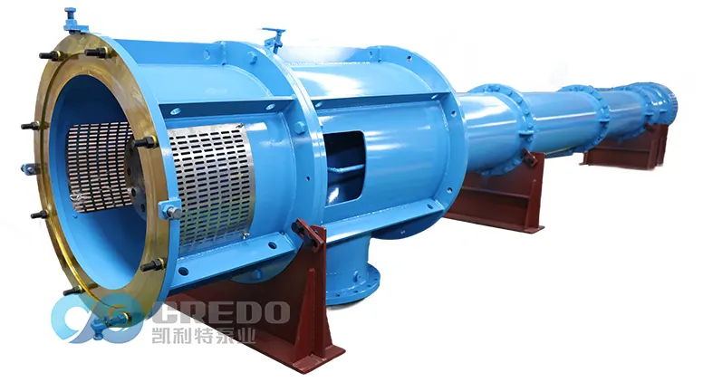
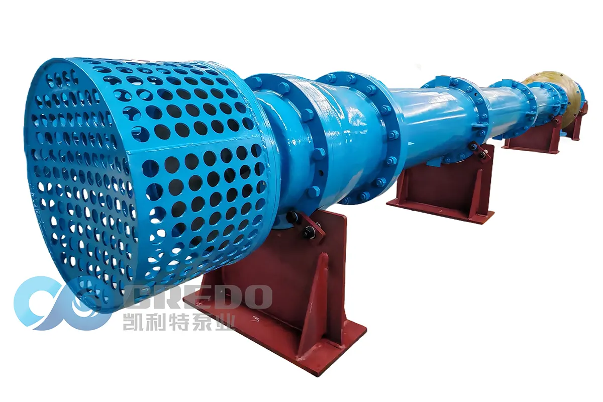
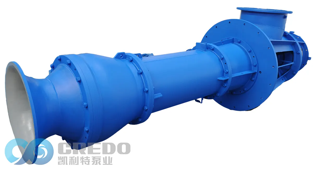
The shaft of a vertical lineshaft turbine pump can extend for tens of meters, with all intermediate line shaft bearings enclosed inside the column pipe. Inspecting an intermediate bearing often requires the column pipe to be dismantled section by section, which can take several days.
If a bearing runs dry, a shaft seizure can occur within minutes, resulting in significant lifting, maintenance, and downtime costs. The purpose of condition monitoring is to turn an unexpected shutdown into planned maintenance.
I. Bearing Temperature Monitoring, Including Shaft Temperature
In engineering practice, “shaft temperature” generally refers to the temperature around the shaft journal and line shaft bearing contact area. It is indirectly measured by a sensor installed at the bearing housing and typically shares the same monitoring circuit as the bearing temperature.
For this reason, the two are discussed together below, with monitoring points classified by bearing location.
1. Sensor Selection and Installation Locations
PT100 / PT1000 RTD (three-wire configuration):
The most commonly used option. It provides high measurement accuracy and compensates for lead resistance, making it suitable for long-term, stable monitoring.
J/K-type thermocouple:
Offers a fast response and good high-temperature capability. Its accuracy is generally lower than that of an RTD, making it suitable for high-temperature or rapidly changing conditions.
Infrared thermometer:
Provides non-contact temperature measurement and is useful for older pumps without embedded temperature sensors. However, readings can be significantly affected by water vapor, so it is mainly suitable for trend monitoring.
Recommended installation locations:
Top thrust bearing housing, which carries the entire hydraulic thrust load
Each intermediate line shaft bearing, especially rubber line shaft bearings, which are more susceptible to heat buildup
Area around the discharge-end mechanical seal chamber, to monitor heat generated by seal friction
2. Temperature Reference Values for Three Types of Bearings
| Bearing Location | Normal Range | Alarm | Shutdown |
| Oil-lubricated thrust bearings / sleeve bearings | 40–70°C | 75°C | 85°C |
| Water-lubricated rubber line shaft bearings | 25–50°C | 60°C | 70°C |
| Motor rolling-element bearings | 40–75°C | 80°C | 95°C |
The values above are general engineering guidelines. Actual limits should be determined according to the manufacturer’s specifications and applicable standards, such as API 610 and ISO 10816.
3. Pay Special Attention to the Rate of Temperature Rise
Regardless of the absolute temperature, a temperature rise of more than 5°C per minute requires immediate investigation.
If the temperature rises together with vibration, this typically indicates bearing wear or damage. If the temperature rises while vibration remains stable, lubrication or cooling problems may be the more likely cause.
II. Mechanical Seal Leakage Monitoring
1. First Identify the Seal Arrangement
Single mechanical seal with flush (API 682 Plan 11/21):
Leakage is discharged to atmosphere and is relatively easy to observe.
Dual mechanical seal with barrier fluid (Plan 53/54):
Seal failure is typically indicated by a drop in barrier-fluid pressure or a decrease in the level of the barrier-fluid reservoir.
Packed stuffing box:
A controlled amount of leakage is normal. The key parameter is the leakage rate rather than whether leakage occurs at all.
2. Four Practical Leakage Detection Methods
| Method | Principle | Typical Application |
| Drip counter / optical leakage detector | Counts the number of drops per minute | Single mechanical seals; simple and cost-effective |
| Liquid collection tank level switch | Triggers an alarm when the liquid level reaches a preset point | Simple and reliable; indicates whether leakage is present |
| Flush or drain line flowmeter | Quantifies the leakage flow rate | Continuous monitoring and data logging for critical pumps |
| Barrier-fluid pressure transmitter | A pressure drop indicates failure of the inboard seal | Dedicated to dual mechanical seal arrangements |
3. Alarm Thresholds
Single mechanical seal:
More than 5–10 drops per minute should be treated as a condition requiring attention. More than 30 drops per minute should trigger a planned shutdown. For toxic, hazardous, or high-temperature fluids, a lower threshold should be considered.
Dual mechanical seal:
A deviation of 10% from the specified barrier-fluid pressure should trigger an alarm.
Cloudy or oil-contaminated leakage water:
This may indicate mechanical seal face wear or leakage of the barrier fluid or lubricating oil. The seal should be inspected as soon as possible.
III. How to Integrate These Monitoring Points into the Existing Control System
Sensors should provide standardized 4–20 mA signals and be connected to the PLC, DCS, or condition monitoring system.
Use two levels of protection:
Warning level: Monitor trends and identify developing problems.
Trip level: Protect the equipment by initiating a shutdown when critical limits are exceeded.
Temperature and vibration should also be analyzed together:
Temperature rising + vibration rising → possible bearing wear or damage
Temperature rising + vibration stable → possible lubrication or cooling problem
Conclusion
So, how should a vertical lineshaft turbine pump actually be monitored?
The basic approach is simple: keep an eye on three key parameters — bearing temperature, mechanical seal leakage, and the rate of temperature rise.
For bearing temperature, PT100 RTDs can be installed in the bearing housings. A typical alarm setting is 75°C for oil-lubricated bearings and 60°C for water-lubricated rubber line shaft bearings.
For mechanical seal leakage, use a drip counter, leakage detector, or pressure transmitter. For a single mechanical seal, leakage above 10 drops per minute should be treated as a condition requiring attention.
Most importantly, remember that threshold values are only protective boundaries. The rate of change is often the more valuable early-warning signal.
Establishing a historical operating baseline for each pump is more useful than relying solely on fixed alarm values. Treat every alarm as an opportunity to understand the equipment better, and a vertical lineshaft turbine pump can move from a “run until failure” approach to proactive, condition-based maintenance.
FAQ
Q: What bearing temperature is considered normal for a vertical lineshaft turbine pump?
A: For oil-lubricated thrust bearings or sleeve bearings, a typical normal range is 40–70°C, with an alarm setting of 75°C. For water-lubricated rubber line shaft bearings, a typical normal range is 25–50°C, with an alarm setting of 60°C.
Water temperature and operating load can affect the measured temperature, so the readings should be evaluated against the pump’s historical operating baseline whenever possible.
Q: How can mechanical seal leakage be detected on a vertical pump?
A: For a single mechanical seal, a drip counter, optical leakage detector, or liquid collection tank level switch can be used. For a dual mechanical seal, monitor barrier-fluid pressure and reservoir level.
The drain line should be routed to a visible collection point so that leakage can be observed and monitored safely.
Related Posts