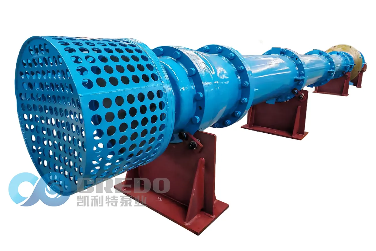
Complete Guide to Vertical Turbine Pump Impeller Wear Repair: Standard Disassembly & Replacement Procedures and Practical Anti-Wear Solutions
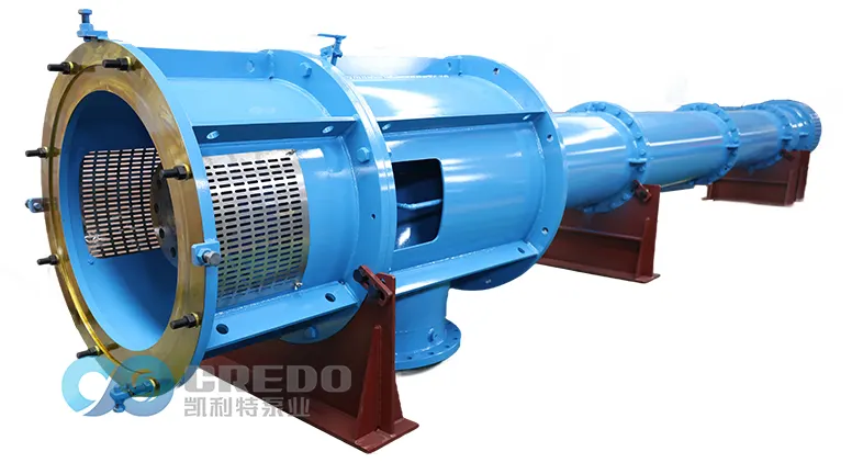
As a core fluid transportation equipment widely used in water conservancy, water supply and drainage systems, industrial circulation, and deep well water intake applications, the vertical turbine pump frequently suffers from impeller wear during operation and maintenance.
This article focuses on common misunderstandings among field technicians (such as the misconception that “vertical turbine pumps cannot experience cavitation”) and provides a systematic explanation of:
Accurate diagnosis methods for impeller wear;
Standardized impeller disassembly and replacement procedures;
Shaft alignment and concentricity correction requirements;
Long-term anti-wear strategies.
The purpose is to help improve pump efficiency, reduce downtime risks, and minimize repair frequency.
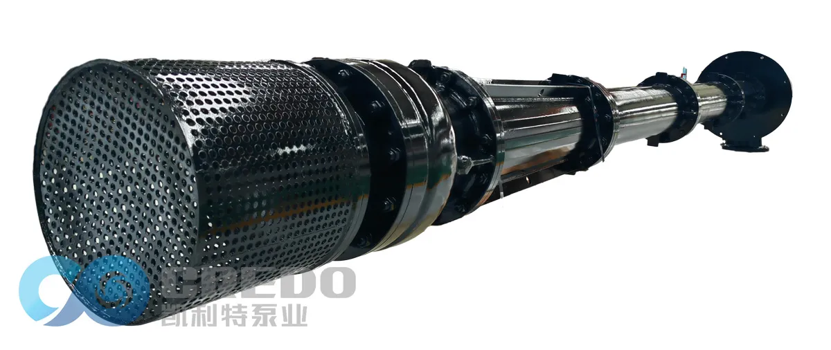
I. Fault Diagnosis: Quickly Identifying Wear and Cavitation
The impeller is the core hydraulic component of a vertical turbine pump, directly affecting pump efficiency, operational stability, and service life.
Accurate identification of failure causes is the first step toward efficient maintenance.
1. Common Fault Symptoms
| Fault Symptom | Possible Causes | Key Features / Inspection Direction | Recommended Solutions |
| Reduced flow rate and decreased head | Abrasive wear, cavitation, impeller blockage | Flow reduction >10%, head reduction >15%; check whether the suction strainer is blocked | Clean or replace the impeller; inspect water quality conditions |
| High vibration and abnormal noise | Loss of dynamic balance, bearing damage, cavitation | Vibration velocity >4.5 mm/s; distinguish between “friction noise” (rubbing contact) and “crackling noise” (cavitation) | Correct shaft alignment; increase submergence depth; replace bearings |
| Abnormal current fluctuation | Impeller rubbing against pump casing, changes in medium density | Unstable current curve; check wear ring clearance | Adjust clearance; check medium concentration |
| Impeller surface damage | Abrasive wear vs. cavitation | Smooth scratches/thinning = wear; honeycomb pits/pitting = cavitation | Improve filtration for abrasive wear; prevent cavitation for cavitation damage |
2. Three Major Causes of Impeller Damage
2.1 Abrasive Wear of Pumping Medium (Most Common)
Water containing sand, sediment, and solid particles causes continuous high-speed erosion of impeller blades and hubs, resulting in abrasive wear.
This is one of the most common failure causes of vertical turbine pumps used in:
Mining drainage;
Municipal water intake;
River pumping stations with high sediment concentration.
2.2 Cavitation Wear (Most Easily Overlooked)
Common Misconception Correction
Many field operators believe:
“The impeller of a vertical turbine pump is always submerged in water, so cavitation cannot occur.”
This understanding is incorrect.
The essence of cavitation is not whether air exists, but whether the local liquid pressure falls below the saturated vapor pressure at the operating temperature.
When this happens, the liquid vaporizes and forms vapor bubbles. When these bubbles collapse, shock waves are generated, causing surface damage to metal components.
Typical Cavitation Conditions in Vertical Turbine Pumps:
Low Water Level:
During deep well pumping, continuous water level decline may reduce impeller submergence depth.
The suction pressure may drop below vapor pressure, causing cavitation.
Blocked Suction Strainer:
When the inlet strainer is clogged by debris:
Flow resistance increases sharply;
Suction pressure decreases;
Cavitation risk increases.
High Temperature Medium:
When pumping hot water or condensate:
Saturated vapor pressure increases with temperature;
Liquid becomes easier to vaporize;
Cavitation becomes more likely.
Excessive Flow Rate:
When the actual operating flow is much higher than the rated design flow:
The inlet velocity increases excessively;
Local pressure drops sharply;
Cavitation may occur at the impeller inlet.
2.3 Improper Installation and Operation
Manufacturing / Assembly Causes:
Impeller installation eccentricity;
Excessive bearing clearance;
Loose impeller locking nut;
Impeller rubbing against pump components.
Operation and Maintenance Causes:
Long-term overload operation;
Frequent start-stop cycles;
Operation outside the rated flow and head range.
These conditions accelerate impeller wear and deformation.
II. Standardized Disassembly and Replacement Procedures
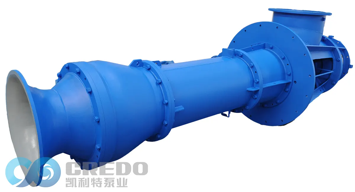
A vertical turbine pump adopts a vertical long-shaft structure, with the impeller located at the bottom section of the pump (deep inside the well).
During disassembly and replacement, the following safety principles must always be followed:
“From top to bottom, outside to inside, power isolation and pressure release first.”
Live-line operation and maintenance under pressure are strictly prohibited.
1. Preparation Work and Tool Checklist
Before starting disassembly, complete all safety preparations and confirm that spare parts are available to avoid extended downtime caused by missing components.
| Category | Items | Specifications / Requirements | Notes |
| Safety equipment | Lockout/Tagout (LOTO) device | Comply with electrical safety regulations | Must be applied after power isolation; live operation is strictly prohibited |
| Lifting equipment | Chain hoist / crane / lifting slings | Load capacity ≥ 1.5 times the total weight of pump shaft assembly | Inspect wire ropes and hooks before operation |
| Critical spare parts | Impeller assembly | Match the pump model and confirm material grade | It is recommended to replace wear rings and seal rings at the same time |
| Sealing components | O-rings, gaskets | High-temperature and corrosion-resistant materials (such as FKM) | Must be replaced with new parts; reused seals are prohibited |
| Fasteners | Locking nuts, lock washers | Strength grade 8.8 or above | Prevent impeller loosening during operation |
| Disassembly tools | Torque wrench, special puller | Properly matched to bolt specifications | Ensure accurate tightening torque |
| Measuring instruments | Dial indicator, feeler gauge | Accuracy: 0.01 mm | Used for shaft alignment correction and clearance measurement |
| Marking tools | Marker pen, center punch | — | Mark flange positions to prevent incorrect reassembly |
2. Step-by-Step Disassembly Procedure (From Top to Bottom)
Step 1: Safe Shutdown and Isolation
Strictly implement the Lockout/Tagout (LOTO) procedure, disconnect the main power supply, and attach warning tags.
Close the inlet and outlet valves, and drain the remaining water inside the pump casing and discharge column pipes.
Inspect lifting equipment (chain hoist, lifting slings, etc.) and confirm that the load capacity meets operational requirements.
Step 2: Remove the Driving Unit
Remove the motor guard and coupling bolts.
Use lifting equipment to remove the motor and place it in a safe area.
Mark the relative installation position between the motor and pump assembly to ensure accurate alignment during reassembly.
Step 3: Remove the Discharge Column Pipes Section by Section
Remove flange bolts of each discharge column pipe section from top to bottom.
Key Tip:
After removing each discharge column pipe flange, use a marker or center punch to make alignment marks (such as A/B/C identification marks).
This ensures that all column pipe sections are reinstalled in their original positions, preventing additional torsional loads on the pump shaft.
Arrange removed column pipes and shaft sections in sequence to avoid mixing components.
Step 4: Remove the Worn Impeller
Lift out the pump shaft assembly and place it steadily on the maintenance support frame.
Secure the shaft end and remove the bottom locking nut using a special wrench.
Remove the worn impeller.
Never directly hammer the impeller, as this may damage the pump shaft.
At the same time, inspect:
Shaft sleeve;
Wear ring;
Seal ring;
Other wearing components.
Step 5: Inspection and Replacement Criteria for Related Components
| Inspection Item | Acceptance Standard | Corrective Action When Exceeded |
| Wear ring clearance | ≤ design value (normally 0.3–0.5 mm) | Replace when clearance >2 mm |
| Shaft sleeve wear | Wear depth <0.2 mm | Replace shaft sleeve if exceeded |
| Pump shaft straightness | Total runout <0.05 mm | Straighten or replace shaft if exceeded |
| Bearing clearance | Meet bearing manufacturer’s standard | Replace if aging or corrosion occurs |
3. Installation and Alignment Correction (The Key Factor Determining Service Life)
3.1 Cleaning and Preparation
Thoroughly clean rust, debris, and old sealing material from the pump shaft fitting surfaces and impeller bore.
Inspect the dynamic balance grade of the new impeller and confirm there are no casting defects.
3.2 Impeller Installation
Install the impeller onto the pump shaft smoothly and ensure proper keyway engagement.
Tighten the locking nut to the specified torque value according to the equipment manual, and install the lock washer for anti-loosening protection.
Do not use excessive force or hammering, as this may deform the impeller bore.
3.3 Step-by-Step Reassembly
Reinstall discharge column pipes, bearing assemblies, and couplings from bottom to top according to the original marks.
Tighten flange bolts evenly in a diagonal sequence to prevent misalignment.
3.4 Shaft Alignment Correction (Critical Step)
Incorrect shaft alignment is the primary cause of:
Impeller rubbing;
Uneven wear;
Excessive vibration.
Alignment Procedure:
Use a dial indicator to measure radial and axial runout between the pump shaft and motor shaft.
Adjust motor base shims to control shaft alignment deviation within: ≤ 0.05 mm
Coupling bolt hole alignment deviation should be: ≤ 0.02 mm
3.5 Replacement of Sealing Components
All O-rings and gaskets must be replaced with new ones.
Reusing old sealing components is strictly prohibited.
Apply an appropriate amount of lubricant during installation to prevent seal twisting and cutting damage.
4. Test Run Verification and Acceptance Criteria
After assembly, the pump must not be directly operated under full load.
The following verification procedures must be completed step by step:
| Verification Step | Operation Requirements | Acceptance Standard | Corrective Action |
| ① Manual rotation test | Rotate coupling manually 3–5 turns | Smooth rotation, no jamming, no abnormal friction noise | Stop and inspect wear ring clearance and foreign objects |
| ② Jog test | Momentarily energize and immediately stop to confirm rotation direction | Rotation direction matches pump marking | Exchange any two motor phases |
| ③ No-load startup | Start with outlet valve closed (closed-valve startup reduces starting current) | Starting current ≤1.5 times rated current | Check voltage and load conditions |
| ④ Load operation | Slowly open outlet valve until reaching operating pressure | Pressure remains within rated head range | Check cavitation or internal recirculation |
| ⑤ Vibration monitoring | Measure vibration at bearing housing in three directions (horizontal/vertical/axial) | Vibration velocity ≤4.5 mm/s | Stop and correct shaft alignment |
| ⑥ Current monitoring | Read operating current from control cabinet display | Operating current ≤ motor rated current | Check valve opening and operating load |
Safety Reminder:
A centrifugal pump must not operate under closed-valve conditions for a long time.
Generally, the closed-valve operation time should not exceed 2–3 minutes.
Otherwise:
Liquid inside the pump may continuously circulate and heat up;
Vaporization may occur;
Mechanical seals may be damaged;
Impeller cavitation damage may be accelerated.
After continuous operation for more than 30 minutes without abnormal conditions, the pump can be returned to normal service.
III. Long-Term Anti-Wear Maintenance Strategies for Vertical Turbine Pump Impellers
Compared with passive repair after failure occurs, preventive protection measures can significantly extend impeller service life and reduce overall maintenance costs.
The following anti-wear system is developed from four key aspects:
Operating condition optimization;
Material upgrade and surface strengthening;
Preventive maintenance planning;
Key maintenance practices.
1. Operating Condition Optimization Strategies
| Optimization Direction | Specific Measures | Applicable Conditions | Implementation Points |
| Ensure sufficient submergence depth | Maintain the first-stage impeller 1.5–2 m below the dynamic water level | Deep well pumps, variable water level conditions | Regularly monitor well water level and install low-water-level alarms |
| Water intake pretreatment | Install filters / cyclone separators / sedimentation tanks | High-sediment water, river intake applications | Clean filters regularly to prevent blockage-induced cavitation |
| Operating parameter control | Strictly operate according to rated flow and head conditions | All operating conditions | Avoid long-term overload operation and frequent start-stop cycles |
| Impeller clearance from well bottom | Maintain distance ≥2–3 m from the well bottom | Deep well installation | Prevent sediment suction and reduce abrasive wear |
2. Comparison of Material Upgrades and Surface Strengthening Solutions
For different wear conditions, selecting suitable materials and surface treatment technologies is the fundamental approach to improving impeller service life.
| Protection Strategy | Specific Measures | Applicable Conditions | Advantages and Disadvantages |
| Ordinary Cast Iron (HT200) | Standard configuration material | Clean water and low-wear applications | Advantages: Low cost; Disadvantages: Low hardness (HB180), poor wear resistance |
| High Chrome Alloy Cast Iron (Cr26) | White cast iron containing more than 26% chromium | Severe abrasive wear, mining drainage applications | Advantages: Hardness HRC58–62, service life increased by 3–5 times; Disadvantages: Higher cost and greater brittleness |
| Duplex Stainless Steel (2205/2507) | Austenitic-ferritic duplex structure | Applications involving both corrosion and wear | Advantages: Excellent corrosion resistance and moderate wear resistance; Disadvantages: High material cost |
| Ceramic Coating Spraying | Plasma spraying of Al₂O₃ / WC coatings | Extreme wear conditions, old component restoration | Advantages: Hardness can exceed HV1200; Disadvantages: Complex process requiring professional equipment |
| Welding Overlay / Laser Cladding | Apply hard alloy layer on blade surfaces | Localized wear repair and life extension of used components | Advantages: Flexible and precise, lower repair cost; Disadvantages: Requires professional equipment and skilled technicians |
3. Preventive Maintenance Schedule
| Maintenance Interval | Maintenance Content | Implementation Standard |
| Daily | Check vibration, noise, current, and discharge pressure | Vibration ≤4.5 mm/s; current ≤ rated value |
| Weekly | Inspect suction strainer cleanliness and bearing temperature | Bearing temperature ≤75℃ |
| Quarterly | Check impeller wear, fastener looseness, and wear ring clearance | Wear ring clearance ≤ design value; locking nuts must remain tight |
| Every Six Months | Perform impeller dynamic balance inspection and pump shaft alignment verification | Dynamic balance grade ≥G6.3 |
| Annual Overhaul | Complete disassembly inspection, replace wearing parts, and evaluate remaining impeller service life | Follow the standardized procedures described in Section 2 |
4. Key Maintenance Points
4.1. Clearance Management
Incorrect impeller wear ring clearance can cause different problems:
Excessive clearance → internal leakage increases → pump efficiency decreases;
Insufficient clearance → impeller rubbing occurs → accelerated blade damage.
The clearance must always be maintained within the manufacturer’s specified range.
4.2 Dynamic Balance Verification
During major maintenance:
Dynamic balance testing of the impeller is recommended;
Eliminate vibration sources;
Reduce bearing load and extend bearing service life.
4.3. Bearing Condition Management
Regularly replace aged bearings.
Excessive bearing clearance may cause:
Pump shaft deflection;
Impeller eccentric rotation;
Rubbing between rotating and stationary components;
Accelerated impeller wear.
IV. Summary
Solving vertical turbine pump impeller wear failures requires a combination of:
“Accurate diagnosis + Precise assembly + Preventive protection”
These three aspects work together to ensure reliable operation.
Accurate Diagnosis
Break the misconception that:
“Vertical turbine pumps cannot experience cavitation.”
Through:
Vibration monitoring;
Surface damage analysis;
Operating condition inspection;
the real failure cause can be accurately identified.
Typical identification method:
Smooth scratches and thinning → abrasive wear
Honeycomb pits and surface erosion → cavitation damage
Different failure mechanisms require completely different solutions.
Precise Assembly
Strictly follow standardized maintenance procedures:
Disassemble from top to bottom;
Mark each component before removal;
Correct shaft alignment within ≤0.05 mm;
Replace all sealing components with new parts.
These measures prevent:
Impeller rubbing;
Excessive vibration;
Premature component failure.
Early Prevention
By implementing:
Proper water intake filtration;
Material upgrades;
Regular preventive maintenance;
wear risks can be minimized before serious failures occur.
Proper repair and maintenance not only solve problems such as:
Insufficient flow;
Abnormal vibration;
Excessive noise;
but also significantly extend the service life of the impeller and the complete vertical turbine pump, ensuring long-term:
Stable operation;
High efficiency;
Low energy consumption.
VI. Related Questions (FAQ)
Q1: Does a worn impeller of a vertical turbine pump always need to be completely replaced?
A: Not necessarily.
If the wear has not damaged the impeller hub and the dynamic balance remains acceptable, repair methods such as:
Welding overlay;
Laser cladding;
can be applied for restoration.
The repair cost is usually only 30%–50% of the cost of a new impeller.
However, if the following conditions occur:
Impeller blades are perforated;
Hub wear is severe;
Deformation exceeds the allowable limit;
it is recommended to replace the impeller directly to avoid affecting pump shaft safety and overall operating reliability.
Q2: How can abrasive wear and cavitation damage be quickly distinguished?
A: Check the surface damage characteristics of the impeller.
Abrasive Wear Characteristics:
Blade edges become thinner;
Surface shows directional and smooth scratches;
Material loss appears gradually due to particle erosion.
Cavitation Characteristics:
Honeycomb-like pits appear;
Sponge-like erosion marks occur;
Severe cases may result in perforation.
The causes and solutions of these two damage types are completely different:
Abrasive wear requires improving filtration and selecting more wear-resistant materials;
Cavitation requires improving suction conditions and preventing pressure drops below vapor pressure.
Q3: What is the recommended distance between the vertical turbine pump impeller and the well bottom?
A: Generally, the recommended installation requirements are:
The impeller should be installed at least 2–3 meters above the well bottom to prevent sediment suction and reduce abrasive wear.
The first-stage impeller should remain 1.5–2 meters below the dynamic water level to avoid air intake and cavitation caused by insufficient submergence.
Q4: Why are vertical turbine pumps prohibited from long-term no-load operation?
A: During closed-valve operation of a centrifugal pump:
The liquid inside the pump continuously circulates under impeller action;
Mechanical energy is converted into heat energy;
The liquid temperature rises rapidly and may eventually vaporize.
This can lead to:
Mechanical seal damage;
Cavitation formation;
Accelerated impeller erosion.
Therefore, closed-valve operation should generally not exceed: 2–3 minutes.
Conclusion
The reliable operation of a vertical turbine pump depends not only on high-quality manufacturing but also on scientific maintenance practices.
By applying:
Accurate fault diagnosis;
Standardized disassembly and replacement procedures;
Correct shaft alignment;
Appropriate material selection;
Preventive maintenance planning;
operators can effectively reduce impeller wear, minimize unexpected downtime, and maintain long-term efficient pump performance.
A well-maintained vertical turbine pump will provide:
Higher operational reliability;
Lower maintenance costs;
Longer service life;
Improved energy efficiency.
Related Posts