Vertical Turbine Pump Operation Guide: Start-Up, Shutdown, Reverse Rotation Prevention, and Troubleshooting
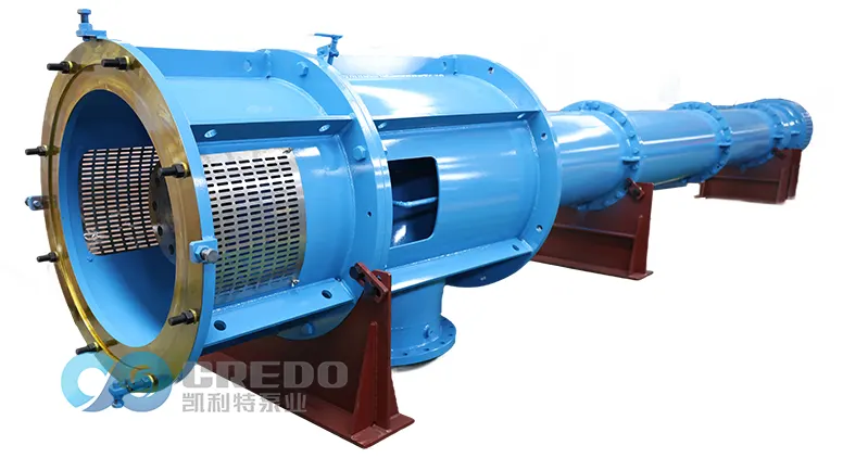
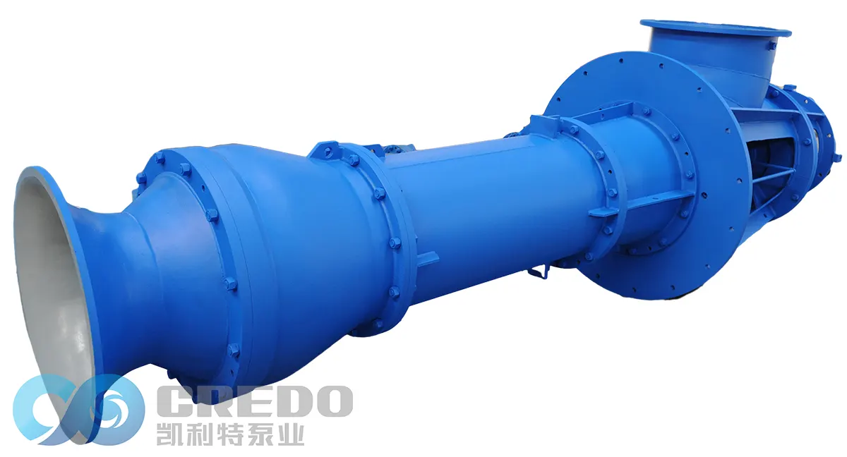
Compared with conventional centrifugal pumps, vertical turbine pumps feature a vertical configuration, long shaft drive system, and submerged suction structure. Due to their extended shaft assembly, multiple rotating components, strict shaft alignment requirements, and guide bearings that often rely on the pumped medium for lubrication, these pumps require more precise operating procedures and maintenance practices.
Proper operation during start-up, shutdown, and abnormal conditions directly affects the service life of critical components, including the pump shaft, bearings, shaft sleeves, and impellers. Improper operation may result in excessive vibration, shaft sleeve seizure, impeller cavitation, reduced hydraulic performance, and unexpected equipment failures.
To improve equipment reliability, minimize operational risks, and ensure long-term stable operation, this guide provides essential operating procedures and precautions based on the structural characteristics of vertical turbine pumps.
1. Start-Up Procedures and Precautions for Vertical Turbine Pumps
The start-up process should always follow the sequence:
Pre-start inspection → Manual shaft rotation → Pump filling and air venting → Rotation check → Controlled start-up → Gradual loading
Never start a vertical turbine pump without proper inspection or when abnormal conditions are identified.
1.1 Pre-Start Inspection Checklist
Before starting the pump, carefully inspect the mechanical system, lubrication system, and auxiliary equipment.
| Inspection Item | Check Requirements |
| Pump shaft | Confirm no visible bending, deformation, or abnormal damage |
| Shaft alignment | Ensure coupling alignment meets technical requirements |
| Bolts and fasteners | Check all foundation bolts and connection bolts are properly tightened |
| Protective guards | Confirm all safety guards are correctly installed |
| Rotating assembly | Verify no abnormal resistance or mechanical interference exists |
| Suction system | Check suction screen and submerged components for blockage or debris |
| Packing gland | Confirm packing compression is properly adjusted |
| Cooling and flushing pipelines | Ensure pipelines are clean and unobstructed |
1.2 Lubrication System Inspection
The lubrication condition of bearings is critical for reliable operation of vertical turbine pumps.
Oil-Lubricated Components
Oil-lubricated components typically include motor bearings and upper thrust bearing assemblies.
| Inspection Item | Requirement |
| Oil level | Maintain oil level within the recommended range, normally between 1/2 and 2/3 of the sight glass |
| Oil quality | Ensure lubricant is clean, clear, and free from contamination, emulsification, or deterioration |
| Bearing housing | Check for leakage or abnormal temperature |
Water-Lubricated Components
The intermediate guide bearings of vertical turbine pumps, such as rubber or thermoplastic bearings, normally rely on the pumped medium for cooling and lubrication.
Before start-up:
| Inspection Item | Requirement |
| Pump column water level | Confirm sufficient water is available for bearing lubrication |
| External flushing water | Open flushing water supply if installed |
| Cooling water flow | Verify flow rate meets design requirements |
| Cooling water pressure | Confirm pressure is within specified range |
Never operate a vertical turbine pump without sufficient lubrication water. Dry running may quickly damage guide bearings and lead to equipment failure.
1.3 Manual Shaft Rotation Check
Before start-up, manually rotate the shaft assembly 2–3 revolutions.
Confirm the following:
| Check Item | Requirement |
| Shaft rotation | Rotor rotates smoothly without resistance |
| Mechanical condition | No abnormal friction, jamming, or unusual noise |
| Rotating clearance | No contact between rotating and stationary components |
This inspection helps identify possible shaft deformation, mechanical interference, or internal damage caused by long-term shutdown.
1.4 Pump Filling and Air Venting
Although many vertical turbine pumps are designed for submerged suction operation, proper air removal is still necessary before operation.
Follow these steps:
| Step | Operation |
| 1 | Open the air vent valve located at the top of the pump assembly |
| 2 | Allow trapped air inside the pump column and piping system to escape |
| 3 | Close the vent valve only after continuous liquid flow is observed |
Proper air venting helps prevent air locking and reduces the risk of cavitation.
1.5 Start-Up and Loading Procedure
Rotation Direction Verification
Before starting the pump:
Perform a brief jog test.
Momentarily energize the motor and stop immediately.
Confirm that the motor rotation direction matches the arrow marked on the pump.
If the rotation direction is incorrect:
Stop operation immediately.
Correct the electrical phase sequence by qualified electrical personnel.
Do not operate the pump in reverse rotation, as it may generate excessive torque loads and damage the shaft system.
Start-Up and Loading Sequence
| Stage | Operation | Purpose |
| 1. Rotation check | Verify motor rotation direction before operation | Prevent reverse rotation damage |
| 2. Initial start-up | Start the motor with the discharge valve fully closed | Reduce starting load and protect motor components |
| 3. Stable operation | Allow motor speed to stabilize | Ensure smooth operation before loading |
| 4. Gradual loading | Slowly open the discharge valve | Bring the pump to the rated operating condition |
| 5. Performance monitoring | Check operating parameters | Confirm safe and stable operation |
Closed-Valve Operation Precautions
Starting with the discharge valve closed reduces motor starting load. However, prolonged closed-valve operation should be avoided.
Normally:
Closed-valve operation should not exceed approximately 3 minutes.
Extended operation may cause internal temperature rise.
Excessive heat generation may lead to vapor formation and cavitation risks.
1.6 Operating Monitoring After Start-Up
After start-up, continuously monitor the pump for at least 5 minutes.
| Monitoring Item | Check Purpose |
| Shaft vibration | Detect alignment issues, imbalance, or bearing problems |
| Operating noise | Identify abnormal mechanical or hydraulic conditions |
| Discharge pressure | Confirm pump performance |
| Motor winding temperature | Prevent overheating |
| Bearing temperature | Verify lubrication and cooling condition |
Only after all operating parameters remain stable should the equipment be transferred to unattended or remote monitoring operation.
2. Shutdown Procedures and Precautions for vertical turbine pumps
The shutdown process of a vertical turbine pump should follow the sequence:
Reduce operating load → Stop the motor → Complete controlled shutdown
Sudden power interruption should be avoided whenever possible, as it may cause water hammer, reverse flow impact, and excessive mechanical stress on the shaft system.
2.1 Normal Shutdown Procedure
Standard Shutdown Sequence
| Step | Operation | Purpose |
| 1 | Slowly close the discharge valve | Gradually reduce hydraulic load and prevent pressure shock |
| 2 | Reduce pump operating load | Minimize impact on the shaft system and sealing components |
| 3 | Stop the motor after the load is reduced | Prevent stopping under high hydraulic load |
| 4 | Maintain flushing or cooling water if required | Allow bearings and shaft sleeves to cool properly |
Shutdown Cooling and Flushing
If an external flushing or cooling water system is installed:
Continue supplying cooling water for several minutes after shutdown.
Follow process requirements to ensure sufficient cooling of guide bearings and shaft sleeves.
This helps prevent:
Bearing overheating
Premature wear
Lubrication failure
2.2 Long-Term Shutdown Protection
When a vertical turbine pump remains out of service for an extended period, additional protection measures are required.
Long-Term Shutdown Checklist
| Inspection / Action | Requirement |
| Valve isolation | Close suction and discharge valves according to operating requirements |
| Drainage | Open the drain valve and completely remove water from the pump column and piping system |
| Freeze protection | Ensure no trapped water remains inside the pump |
| Corrosion prevention | Keep internal components dry to reduce corrosion risk |
| Packing protection | Slightly loosen packing gland to prevent sticking between packing and shaft sleeve |
Reasons for Proper Drainage During Long-Term Shutdown
Failure to drain the pump properly may result in:
| Risk | Possible Consequence |
| Freezing water | Pump column or piping cracking |
| Standing water | Internal corrosion |
| Frozen packing | Shaft sleeve sticking or start-up difficulty |
| Moisture accumulation | Reduced component service life |
2.3 Periodic Shaft Rotation During Extended Shutdown
For vertical turbine pumps that remain idle for long periods:
| Maintenance Action | Recommended Practice |
| Manual shaft rotation | Rotate the shaft assembly approximately 180° once a week |
| Purpose | Prevent permanent shaft bending caused by continuous static loading from the rotating assembly weight |
Regular shaft rotation helps maintain mechanical integrity before the next start-up.
2.4 Emergency Shutdown Procedure
Immediately stop the pump when any of the following abnormal conditions occur:
| Emergency Condition | Required Action |
| Excessive vibration exceeding alarm limits | Stop operation and inspect shaft alignment and bearings |
| Abnormal mechanical noise | Shut down and investigate rotating components |
| Sudden increase in motor current | Disconnect power and check overload causes |
| Motor overheating or smoke emission | Stop immediately and inspect electrical and cooling systems |
| Overload protection activation | Identify and eliminate the cause before restarting |
Emergency Shutdown Steps
Press the emergency stop button or disconnect power immediately.
Close relevant valves if required by the system design.
Identify and correct the cause of failure.
Restart the pump only after completing inspection and troubleshooting.
A vertical turbine pump must not be restarted until the cause of the abnormal condition has been fully identified and eliminated.
3. Reverse Rotation Prevention for Vertical Turbine Pumps
Reverse rotation is a serious abnormal operating condition for vertical turbine pumps.
Due to their long and slender shaft structure, reverse rotation can generate excessive mechanical stress and may result in:
| Potential Damage | Consequence |
| Shaft deformation | Permanent bending or distortion of the pump shaft |
| Shaft sleeve wear | Severe surface damage or seizure |
| Impeller nut loosening | Risk of impeller displacement |
| Coupling damage | Possible coupling failure |
vertical turbine pumps must never be operated under reverse rotation conditions.
3.1 Preventive Rotation Verification
Rotation direction must always be checked before the first start-up after:
Equipment maintenance
Motor rewiring
Power restoration after an outage
Rotation Check Checklist
| Inspection Item | Requirement |
| Pump rotation direction | Must match the arrow marked on the pump |
| Motor phase sequence | Must be correctly connected |
| Jog test | Perform brief start-stop verification before full operation |
3.2 Reverse Rotation Handling During Operation
If reverse rotation occurs during operation, immediate action is required.
Possible Signs of Reverse Rotation
| Symptom | Possible Indication |
| Discharge pressure suddenly drops to zero | Pump is no longer producing normal flow |
| Abnormal current indication | Motor load condition changes |
| Unusual water flow noise | Reverse flow or hydraulic instability |
Reverse Rotation Emergency Response
| Step | Action |
| 1. Stop the pump | Immediately disconnect power to stop the motor |
| 2. Prevent backflow | Close the discharge valve if necessary |
| 3. Inspect check valve | Verify check valve operation and sealing condition |
| 4. Check electrical system | Confirm motor phase sequence and wiring |
| 5. Investigate pipeline conditions | Check for abnormal pressure loss or leakage |
| 6. Restart only after correction | Resume operation only after the root cause is eliminated |
Prohibited Actions During Reverse Rotation
Never:
Open the discharge valve while the pump is rotating backward.
Restart the motor without correcting the cause.
Force the motor to start against reverse rotation.
These actions may create excessive reverse torque and cause severe damage to the shaft system, impeller, or coupling.
4. Special Operating Conditions for Vertical Turbine Pumps
vertical turbine pumps installed in outdoor or demanding environments require additional protection measures to maintain reliable operation under special conditions.
4.1 Flood Season Protection
Before heavy rainfall or potential flooding conditions, inspect both the electrical system and pump station environment.
Electrical Protection Checklist
| Inspection Item | Requirement |
| Motor insulation resistance | Verify insulation resistance meets electrical safety requirements (normally ≥0.5 MΩ) |
| Motor terminal box | Ensure sealing rings are intact and properly installed |
| Cable entry points | Confirm all cable openings are properly sealed |
| Motor protection | Prevent rainwater from entering through cable openings or shaft areas |
Pump Station Protection Checklist
| Inspection Item | Requirement |
| Drainage system | Ensure drainage channels are clean and unobstructed |
| Sump level | Maintain water level within the safe operating range |
| Pump foundation area | Prevent water accumulation around electrical equipment |
| Motor protection | Avoid motor flooding caused by rising water levels |
4.2 Winter Freeze Protection
For outdoor-installed vertical turbine pumps operating in freezing environments, proper drainage is essential during shutdown periods.
Freeze Protection Checklist
| Risk | Preventive Action |
| Residual water freezing inside the pump | Open drain valves and completely remove remaining water |
| Pump column damage | Prevent trapped water from freezing and expanding |
| Pipeline cracking | Drain connected piping systems when required |
| Internal component damage | Keep the pump dry during extended shutdown periods |
Frozen water expands significantly and may cause:
Pump column cracking
Pipeline damage
Deformation of internal components
5. General Safety Requirements for Vertical Turbine Pump Operation
Safe operation of vertical turbine pumps depends on:
Proper operating procedures
Qualified personnel
Continuous equipment monitoring
Preventive maintenance practices
All operators should strictly follow the safety requirements below to reduce operational risks and ensure reliable equipment performance.
5.1 Qualified Personnel Requirements
| Safety Item | Requirement |
| Operation personnel | Only trained and qualified operators are permitted to operate the equipment |
| Maintenance personnel | Inspection and repair work must be performed by authorized personnel |
| Unauthorized operation | Operation by untrained personnel is strictly prohibited |
5.2 Personal Protective Equipment (PPE)
During operation and maintenance:
| Safety Item | Requirement |
| Head protection | Wear a safety helmet when working around pump equipment |
| Foot protection | Wear appropriate safety footwear |
| Elevated platform access | Use handrails and maintain secure footing |
| Rotating components | Never touch shafts, couplings, or other rotating parts during operation |
| Electrical safety | Never perform maintenance on energized equipment |
| Pressure safety | Never disassemble components while the system is pressurized |
5.3 Smooth and Controlled Operation
During start-up, shutdown, and valve adjustment:
| Operating Practice | Purpose |
| Open and close valves slowly | Reduce hydraulic shock |
| Avoid sudden start-stop cycles | Minimize mechanical stress |
| Maintain stable operating conditions | Protect shaft system and hydraulic components |
| Avoid abrupt load changes | Reduce water hammer risk |
Controlled operation helps reduce:
Hydraulic shock
Water hammer
Excessive stress on the rotating assembly
5.4 Regular Inspection and Condition Monitoring
Routine inspection should focus on the following items:
| Monitoring Item | Purpose |
| Shaft alignment | Detect mechanical deviation and prevent vibration |
| Bearing temperature | Verify lubrication and cooling conditions |
| Shaft vibration | Identify imbalance, misalignment, or bearing wear |
| Check valve performance | Prevent reverse flow and reverse rotation |
| Lubrication condition | Ensure reliable bearing operation |
| Shaft seal leakage | Detect sealing problems early |
Maintaining equipment operating records and condition monitoring data helps identify potential issues at an early stage and prevents unexpected failures.
6. Common Faults and Troubleshooting Methods for Vertical Turbine Pumps
The following table provides common operating problems, possible causes, and recommended solutions.
| Fault Symptom | Possible Causes | Recommended Solutions |
| Pump starts but no water is delivered | 1. Suction screen blockage 2. Incorrect motor rotation direction 3. Air trapped inside pump system | 1. Clean suction screen and remove debris 2. Stop pump and correct motor phase sequence 3. Open vent valve and remove trapped air |
| Excessive vibration or abnormal noise | 1. Shaft alignment deviation 2. Bearing wear or damage 3. Cavitation 4. Impeller imbalance | 1. Check and correct shaft alignment 2. Replace damaged guide or thrust bearings 3. Improve suction conditions and increase inlet water level 4. Perform impeller balancing or replacement |
| High motor current or overload trip | 1. Packing gland over-tightened 2. Bearing lubrication failure 3. Impeller contact with wear ring 4. Pumped medium density exceeds design condition | 1. Adjust packing compression 2. Add lubricant or replace bearings 3. Check internal clearances and repair components 4. Verify actual operating parameters |
| Packing area overheating or excessive leakage | 1. Cooling water interruption 2. Uneven packing gland adjustment 3. Shaft sleeve wear | 1. Restore cooling water supply 2. Adjust gland bolts evenly 3. Replace shaft sleeve or repack |
| Unstable discharge pressure | 1. Low suction water level 2. Air leakage in suction pipeline 3. Unstable rotational speed | 1. Increase water level or improve suction conditions 2. Check and seal suction pipeline connections 3. Inspect power supply and variable frequency drive |
Conclusion
Reliable operation of a vertical turbine pump depends on correct procedures, regular inspection, and proper maintenance practices.
Following standardized start-up, shutdown, and troubleshooting procedures helps:
Reduce equipment failures
Extend component service life
Improve operational reliability
Maintain stable hydraulic performance
By implementing disciplined operating practices and continuous condition monitoring, vertical turbine pumps can deliver safe, efficient, and long-term performance in demanding industrial applications.
FAQ – for Vertical Turbine Pump
Learn about the key spare parts commonly used in vertical turbine pumps.
| Vertical Turbine Pump Spare Parts & Qty (2 Years) | ||||||||
| For Packing Seal Pump | ||||||||
| Spare Parts/Qty | Pump Qty (Including Spare Pump) | |||||||
| 1 | 2 | 3 | 4 | 5 | 6 | 8 | ≥10 | |
| Shaft Sleeve(Packing) | 1 | 2 | 3 | 3 | 5 | 5 | 7 | 8 |
| Shaft Sleeve(Middle) | 1 | 2 | 3 | 3 | 5 | 5 | 7 | 8 |
| Shaft Sleeve(Lower) | 1 | 2 | 3 | 3 | 5 | 5 | 7 | 8 |
| Packing | 1 | 2 | 3 | 3 | 5 | 5 | 7 | 8 |
| O Ring | 1 | 2 | 3 | 3 | 5 | 5 | 7 | 8 |
| Wear Ring | 1 | 2 | 3 | 3 | 5 | 5 | 7 | 8 |
| Adapter Coupling | 1 | 2 | 3 | 3 | 5 | 5 | 7 | 8 |
| Guide Bearing | 1 | 2 | 3 | 3 | 5 | 5 | 7 | 8 |
| Bearing | 1 | 2 | 3 | 3 | 5 | 5 | 7 | 8 |
| Impeller Shaft | 1 | 1 | 1 | 2 | 2 | 3 | 4 | 5 |
| Middle Shaft | 1 | 1 | 1 | 2 | 2 | 3 | 4 | 5 |
| Transmission Shaft | 1 | 1 | 1 | 2 | 2 | 3 | 4 | 5 |
| Impeller | 1 | 1 | 1 | 2 | 2 | 3 | 4 | 5 |
| Packing Gland | 1 | 1 | 1 | 2 | 2 | 3 | 4 | 5 |
| For Mechanical Seal Pump | ||||||||
| Spare Parts/Qty | Pump Qty (Including Spare Pump) | |||||||
| 1 | 2 | 3 | 4 | 5 | 6 | 8 | ≥10 | |
| Shaft Sleeve(Mechanical Seal) | 1 | 2 | 3 | 3 | 5 | 5 | 7 | 8 |
| Shaft Sleeve(Middle) | 1 | 2 | 3 | 3 | 5 | 5 | 7 | 8 |
| Shaft Sleeve(Lower) | 1 | 2 | 3 | 3 | 5 | 5 | 7 | 8 |
| Mechanical Seal | 1 | 2 | 3 | 3 | 5 | 5 | 7 | 8 |
| O Ring | 1 | 2 | 3 | 3 | 5 | 5 | 7 | 8 |
| Wear Ring | 1 | 2 | 3 | 3 | 5 | 5 | 7 | 8 |
| Adapter Coupling | 1 | 2 | 3 | 3 | 5 | 5 | 7 | 8 |
| Guide Bearing | 1 | 2 | 3 | 3 | 5 | 5 | 7 | 8 |
| Bearing | 1 | 2 | 3 | 3 | 5 | 5 | 7 | 8 |
| Impeller Shaft | 1 | 1 | 1 | 2 | 2 | 3 | 4 | 5 |
| Middle Shaft | 1 | 1 | 1 | 2 | 2 | 3 | 4 | 5 |
| Transmission Shaft | 1 | 1 | 1 | 2 | 2 | 3 | 4 | 5 |
| Impeller | 1 | 1 | 1 | 2 | 2 | 3 | 4 | 5 |
| Mechanical Seal Gland | 1 | 1 | 1 | 2 | 2 | 3 | 4 | 5 |
| Under harsh operating conditions, the quantity of spare parts should be doubled. | ||||||||
Discover how to select the right vertical turbine pump materials based on fluid properties and operating conditions.
| Pump Parts | For Clear Water | For Sewage | For Seawater |
| Discharge Elbow / Casing | Carbon Steel | Carbon Steel | S.S / Super Dulex |
| Diffuser / Suction Bell | Cast Iron | Cast Iron / Ductile Iron / Cast Steel / S.S | S.S / Super Dulex |
| Impeller / Impeller Chamber / Wear Ring | Cast Iron / Cast Steel | Ductile Iron / S.S | S.S / Super Dulex |
| Shaft / Shaft Sleeve / Coupling | Steel / S.S | Steel / S.S | S.S / Super Dulex |
| Guide Bearing | PTFE / Thordon | ||
| Remark | Final material depends on the liquid condition or the client’s request. | ||
Follow the essential installation steps to ensure safe and reliable operation of the vertical turbine pump.
| Standardized Installation Procedure for Vertical Turbine Pump | |||
| Work Stage | No. | Main Steps | Key Operations & Notes |
| I. Pre-Installation Preparation | 1 | Site & Foundation Inspection | • Clean the wellhead or pit, ensure no debris. Check foundation (well or concrete pedestal) verticality, levelness, and dimensions meet drawings. • Verify positions and specifications of anchor bolts or embedded parts. |
| 2 | Equipment Unpacking & Inspection | • Count all items according to packing list: motor, pump base, drive shaft, delivery pipe, guide bearing housing, impeller, coupling, etc. • Check all parts for transport damage, especially drive shaft threads, keyways, and flanges of delivery pipe. | |
| 3 | Tools & Material Preparation | • Prepare lifting equipment (hoist, crane), special wrenches, level, dial indicator, plumb line, lubricant (oil/grease), raw tape, lifting beams, etc. • Prepare cleaning agents and cloths. | |
| II. Pump Casing & Shaft Installation | 4 | Install Pump Base & Outlet Elbow | • Lift pump base onto foundation, preliminarily position, insert anchor bolts but do not tighten. • Install outlet elbow and connect outlet piping. |
| 5 | Install First Section of Delivery Pipe & Drive Shaft | • Lift the first delivery pipe section, install guide bearing housing at lower end, slowly lower to pass through pump base and preliminarily connect. • Insert drive shaft from top of delivery pipe, connect lower end via coupling to pump shaft (or next shaft section). Ensure firm keyway connection and install drive shaft protective tube. • Core: maintain verticality and concentricity. Each section must be checked with level or plumb line (typical tolerance ≤2 mm/m). | |
| 6 | Install Delivery Pipe Sections & Drive Shaft | • Install guide bearings in each pipe section (water or grease lubricated) ensuring drive shaft passes through center. • Connect each drive shaft section, ensure keyway/coupling connection is firm and concentric. Check rotation manually for smoothness. | |
| 7 | Install Final Impeller & Suction Bell | • Install final stage impeller, adjust axial clearance via upper drive shaft adjustment nut (refer to manufacturer’s manual). • Install suction bell. | |
| III. Alignment, Grouting & Motor Installation | 8 | Overall Alignment & Primary Grouting | • Use pump base as reference, check overall verticality with level. • Perform primary grouting, fix anchor bolts. Wait until grout fully cures (usually 3–7 days). |
| 9 | Install Motor & Alignment | • Lift motor onto base. • Key alignment: use dial indicator to adjust motor and drive shaft coaxiality (radial deviation ≤0.05 mm) to reduce vibration and wear. Tighten motor anchor bolts after alignment. | |
| 10 | Install Coupling & Guard | • Install coupling and connections, install protective guard. | |
| IV. Piping & Accessories Installation | 11 | Lubrication & Sealing System | • For grease-lubricated guide bearings, inject specified grease via lubrication line. • For water-lubricated guide bearings, connect water pipes and ensure clean water supply. • Connect pump base stuffing box or mechanical seal cooling/flushing water lines. |
| 12 | Electrical & Instrumentation Installation | • Connect motor power cables, install ammeter, temperature sensors, etc. • Install outlet pressure gauge, flow meter. | |
| V. Post-Installation Inspection & Test Run | 13 | Final Checks | • Manual rotation: rotate motor-coupling system, check smoothness, flexibility, and absence of binding. • Check all connection bolts are tightened. • Jog motor: confirm rotation direction (typically clockwise from top view). |
| 14 | Priming & Test Run | • Fill pump with delivery medium (for deep well pump, pre-lubricate via auxiliary pipe and stuffing box). • Start: close outlet valve, start motor. • Commissioning: slowly open outlet valve, monitor current, pressure, flow, vibration, bearing temperature, and check stuffing box leakage (droplet form preferred). Test run ≥2 hours. | |
Explore proper disassembly and maintenance procedures to maximize the vertical turbine pump service life.
| Standardized Disassembly & Maintenance Procedure for Vertical Turbine Pump | |||
| Work Stage | No. | Main Steps | Key Operations & Notes |
| I. Pre-Disassembly Preparation | 1 | Shutdown & Isolation | • Safety first: slowly close the outlet valve, cut off power, and apply lockout/tagout (LOTO). • Close the inlet valve, open pump vent, drain pump and piping. For deep well pumps, lower water level below pump suction. |
| 2 | Disconnect External Connections | • Disconnect motor power cables. • Remove coupling bolts and guard. • Disconnect all connected pipelines (lubrication, cooling, pre-lubrication water pipes) and seal pipe ends. | |
| 3 | Tools & Preparation | • Prepare lifting equipment (tripod, hoist), shaft clamps, special wrenches, marking pens, parts boxes. • Prepare shaft support frame for placing removed long shaft. | |
| II. Pump Casing Disassembly (Top to Bottom) | 4 | Remove Motor & Pump Base Accessories | • Lift motor and place safely. • Remove stuffing box covers or mechanical seal, lubrication pipe fittings, and other accessories. |
| 5 | Remove Drive Shaft Adjustment Mechanism | • Loosen and remove adjustment nuts and shaft end fixing devices. | |
| 6 | Lift Drive Shaft & Delivery Pipe Sections | • Core: lift in sections to prevent bending and dropping. • Use shaft clamp to support top section of drive shaft, lift a short distance to disconnect from next shaft coupling. • Place removed shaft sections horizontally on support; do not lean. • Disconnect top delivery pipe flange from pump base and lift out the section. • Repeat for all shaft and pipe sections. Number each section sequentially. | |
| 7 | Lift Impeller & Suction Components | • Lift final-stage impeller, guide vane assembly, and suction bell. | |
| III. Parts Cleaning, Inspection & Measurement | 8 | Cleaning, Inspection & Measurement | • Thoroughly clean all parts. Key checks: – Drive shaft: straightness, keyway wear, surface corrosion. – Coupling: check keyway, end faces. – Impeller: cavitation, wear, corrosion, dynamic balance if necessary. – Guide bearings (rubber or metal): check inner diameter, replace if worn. – Delivery pipe: flange surfaces, internal corrosion, scaling. – Seals: check stuffing box or mechanical seal wear. |
| IV. Reassembly (Reverse Order) | 9 | Reassembly | • Core principle: clean, align, vertical, tighten section by section. • Replace all damaged O-rings, gaskets, guide bearings. • Start from lowest suction component, reinstall delivery pipes and drive shaft sequentially. Check drive shaft flexibility and delivery pipe verticality. • Install impeller, adjust axial clearance via upper adjustment nut to manufacturer specification. • Reinstall motor and perform precise alignment (same as installation standard). • Install stuffing box or mechanical seal, adjust gland tightness. |
| V. Final Verification | 10 | Final Inspection & Test Run | • Manual rotation: rotate coupling system, check entire long shaft assembly moves freely. • Connect all pipelines, inject grease or start lubrication water. • Follow “Priming & Test Run” procedure from installation, paying attention to vibration and current after start-up. |
Find practical solutions to the most common vertical turbine pump operating issues.
| Common Faults and Solutions for Vertical Turbine Pump | |||
| No. | Problems | Causes | Solutions |
| 1 | Pump cannot start | 1. Power failure (power off, phase missing, voltage too low). 2. Motor failure (stator short circuit, wiring error). 3. Pump shaft jammed, bearing seized, or foreign object inside. 4. Start conditions not met (e.g., deep well pump not pre-lubricated). 5. Packing gland too tight. | 1. Check power, switch, fuses; restore three-phase voltage. 2. Inspect and repair motor, correct wiring. 3. Manually rotate, clean debris, replace seized bearings. 4. Add sufficient pre-lubrication water as per procedure. 5. Loosen packing gland appropriately. |
| 2 | Insufficient flow or no water | 1. Suction filter, impeller, guide vane body, or piping blocked. 2. Insufficient submergence, air suction causing cavitation. 3. Wrong motor rotation. 4. Seal ring (wear ring) worn or impeller damaged. 5. Low speed (voltage/frequency mismatch). 6. Water level drops, suction bell exposed. 7. Discharge pipe broken or leaking. 8. System resistance mismatch. | 1. Clean filter, impeller, guide vane, and piping. 2. Lower installation height, increase water level (>1 m recommended). 3. Swap any two motor phase wires to correct rotation. 4. Replace worn seal ring or impeller. 5. Check voltage/frequency; ensure rated speed. 6. Increase submergence or extend delivery pipe. 7. Inspect and repair discharge pipe and connections. 8. Recalculate system conditions to ensure efficient operation. |
| 3 | Low head / low pressure | 1. Wrong impeller stages or severe wear. 2. Low speed. 3. Cavitation. 4. Seal ring worn, high internal leakage. 5. Excessive pipeline resistance (valves partially closed, too many elbows, small diameter). | 1. Check impeller stages, replace worn impeller. 2. Check voltage/frequency, increase to rated speed. 3. Increase inlet pressure, improve suction conditions, prevent cavitation. 4. Replace worn seal ring. 5. Fully open outlet valves, optimize piping layout and diameter. |
| 4 | Severe vibration, abnormal noise | 1. Insufficient submergence, cavitation (high-frequency popping sound). 2. Impeller unbalanced (scaling, wear, deformation). 3. Drive shaft misalignment, bent or excessive intermediate bearing spacing. 4. Pump-motor shaft misalignment. 5. Bearing (including guide bearing) damaged or excessive clearance. 6. Uneven foundation, loose anchor bolts. 7. Improper support of discharge pipe. 8. Operation near critical speed. | 1. Increase suction water level, ensure proper submergence. 2. Clean impeller, perform dynamic balancing. 3. Correct shaft concentricity; straighten or replace bent shaft; install and tighten intermediate bearing brackets. 4. Use dial indicator to correct coaxiality (≤0.05 mm). 5. Replace damaged bearings and worn guide bearings. 6. Re-level foundation, tighten all anchor bolts. 7. Check and reinforce pipe supports; avoid resonance frequency. 8. Adjust operating speed to avoid critical region. |
| 5 | Motor overload (high current) | 1. Low supply voltage. 2. Bearing damage, impeller rubbing seal ring or casing. 3. Pump suction blocked with sand or debris. 4. Flow too high. 5. Packing gland too tight. 6. Single-phase operation due to supply line fault. | 1. Start when supply voltage normal. 2. Replace bearings; check and adjust impeller axial clearance. 3. Stop pump, clean sand/debris. 4. Adjust outlet valve to limit flow to rated range. 5. Loosen packing gland appropriately. 6. Professional electrician inspect and repair supply. |
| 6 | Bearing overheating (including motor bearings) | 1. Insufficient lubrication or grease aging/deterioration, wrong type. 2. Bearing contaminated by water, lubrication failure. 3. Incorrect bearing clearance (too small or too large). 4. Long shaft misalignment, radial load on bearing. 5. Bearing damage. 6. Speed exceeds bearing limit. | 1. Refill or replace qualified waterproof grease (high speed ~400 h, low speed ~600 h). 2. Replace grease, repair water ingress seal. 3. Adjust bearing clearance per manufacturer. 4. Re-align long shaft system. 5. Replace bearing. 6. Control speed within allowed limit. |
| 7 | Severe shaft seal leakage (mechanical seal) | 1. Seal face wear, scaling. 2. Seal water pressure insufficient or interrupted (0.1–0.3 MPa). 3. Excessive shaft axial movement. 4. Installation deviation. 5. Particles in medium causing seal wear. | 1. Grind seal face or replace mechanical seal. 2. Ensure stable seal water supply. 3. Repair thrust bearing, control shaft axial movement. 4. Realign and standardize installation. 5. Install inlet filter, purify medium. |
| 8 | Severe shaft seal leakage (packing) | 1. Packing worn, aged. 2. Gland too loose or uneven, too tight. 3. Shaft or sleeve damaged, bent. 4. Insufficient lubrication/cooling water. 5. Medium contains high sand content. | 1. Replace packing (check every 2000 h). 2. Evenly tighten gland, adjust to slow drip. 3. Repair, polish, or replace shaft/sleeve. 4. Ensure clean cooling/lubrication water. 5. Purify water; replace sleeve if necessary. |
| 9 | Long shaft axial movement / large axial vibration | 1. Thrust bearing wear. 2. Incorrect shaft end clearance. 3. Loose or poorly lubricated coupling. 4. Vertical deviation of delivery pipe. | 1. Inspect and replace thrust bearing. 2. Adjust shaft end clearance per manufacturer. 3. Tighten and lubricate coupling. 4. Correct verticality of delivery pipe (≤2 mm/m). |
| 10 | Sudden increase in operating power | 1. Impeller axial clearance too small, rubs guide vanes. 2. Sand in water causing blockage. 3. Motor bearing damaged. | 1. Stop pump, adjust impeller axial clearance. 2. Dismantle and clean pump, improve water quality. 3. Replace motor bearing. |
| 11 | Pump body or connection leakage | 1. Pump seals (O-ring, gasket) aged or damaged. 2. Loose or uneven bolts. 3. Casting defects (porosity, cracks). | 1. Replace damaged seals. 2. Tighten all bolts evenly. 3. Repair defects; replace pump body if severe. |
| 12 | Delivery pipe or drive shaft breakage | 1. Material defect, fatigue, or corrosion. 2. Misalignment causing additional bending. 3. Operation in resonance zone. 4. Water hammer. | 1. Replace with qualified material, apply anti-corrosion treatment. 2. Ensure coaxial alignment during installation. 3. Eliminate vibration source, avoid resonance. 4. Install water hammer eliminator or slow-closing check valve. |
| 13 | Deep well pump-specific faults | 1. Cable or joint water ingress. 2. Motor chamber not filled with clean pre-lubrication water. 3. Phase missing or long-term overload. | 1. Repair or replace waterproof cable/joints. 2. Ensure motor chamber always filled with clean water. 3. Check protection devices, avoid phase loss and overload. |
Learn the maintenance practices that help improve vertical turbine pump reliability and reduce downtime.
| Daily Maintenance and Care for Vertical Turbine Pump | ||
| Maintenance Category | Maintenance Item | Detailed Content & Standards |
| I. Pre-Operation Inspection | 1. Appearance & Connection Inspection | • Check pump, motor, pipelines, and pipe joints for looseness, leakage, damage, or deformation. • Check whether anchor bolts, coupling guards, and other fasteners are secure. |
| 2. Lubrication System Inspection | • Oil lubrication: Check whether the oil level in the bearing housing is at the centerline of the oil sight glass and whether the oil is clean and transparent. Replace immediately if emulsified, discolored, or contaminated. • Grease lubrication: Check whether grease quantity is sufficient. It is recommended to use special waterproof or water-resistant grease. | |
| 3. Manual Rotation & Rotation Direction Confirmation | • Manual turning: Rotate the coupling manually to check whether the rotor rotates flexibly and evenly without abnormal friction noise. • Jogging rotation check: Jog the motor to confirm that the rotation direction matches the arrow indicated on the pump. | |
| 4. Sealing & Priming Water | • Check whether the cooling/flushing water system of the mechanical seal is unobstructed and whether the pressure is normal (recommended 0.1–0.3 MPa). • For packing seals, check the gland tightness. • Open the pump vent plug, fill the pump with liquid, and completely vent the air inside the pump. | |
| II. Monitoring During Operation | 1. Operating Parameter Monitoring | • Pressure & flow: Monitor outlet pressure and flow to ensure operation within the rated range on the pump nameplate for optimal efficiency. • Motor current & temperature: Motor current should remain within the rated range; motor surface temperature should not be excessively high. |
| 2. Bearing Condition Monitoring | • Temperature: Bearing temperature should not exceed ambient temperature by 35°C, and the maximum temperature should not exceed 80°C. • Vibration: Measure vibration regularly. At 1800 r/min, vibration velocity RMS should generally not exceed 4.5 mm/s. | |
| 3. Seal Leakage Monitoring | • Mechanical seal: Normal leakage should not exceed 5 drops/minute. • Packing seal: Adjust the gland to maintain leakage at approximately 30–60 drops/minute. Adjust if leakage is too much or too little. | |
| 4. Abnormal Noise & Vibration Monitoring | • Monitor operating sound. Normal sound should be stable and uniform. If severe friction, knocking, or periodic vibration occurs, stop the pump immediately for inspection. | |
| III. Periodic Maintenance (Preventive) | 1. Lubrication Management | • Oil change cycle: Change oil after the first 100 hours of operation, then every 500 hours thereafter. Depending on speed: high-speed pumps (2900 rpm) every 400 hours; low-speed pumps (1450 rpm) every 600 hours. • Grease replenishment: Replenish regularly; inspect grease condition every 200 hours of operation. |
| 2. Shaft Seal System Maintenance | • Packing seal: Regularly adjust gland tightness. “Three-finger method”: slight resistance during manual rotation is appropriate. Replace packing approximately every 2000 operating hours. • Mechanical seal: Check flushing water pressure and flow to ensure clean water continuously passes through the seal faces. | |
| 3. Bearing & Shaft Sleeve Inspection | • Regularly inspect wear of guide bearings and thrust bearings. • Inspect shaft sleeve wear and replace promptly if severe. | |
| 4. Impeller & Clearance Inspection | • Inspect impeller for cavitation, corrosion, wear, or scaling, and clean flow passages. • Check the clearance between impeller and seal ring (wear ring). Allowable deviation is generally ≤0.5 mm; replace if worn beyond the limit. | |
| 5. Alignment & Tightening | • Regularly inspect and correct alignment between pump shaft and motor shaft (deviation requirement generally ≤0.05 mm). • Retighten all anchor bolts and pipeline connections. | |
| 6. Electrical & Pipeline Inspection | • Regularly inspect motor insulation performance. • Check whether valves operate flexibly, whether pipe supports are secure, and clean inlet filters. | |
| IV. Long-Term Shutdown & Seasonal Maintenance | 1. Winter Freeze Protection | • When ambient temperature is below 0°C, drain all liquid from the pump and cooling water system to prevent freezing and cracking. |
| 2. Long-Term Shutdown Maintenance | • Drain the medium inside the pump and thoroughly clean the pump body and flow passages. • Disassemble the pump, wipe all parts clean, apply anti-rust oil to rotating and mating surfaces, and reinstall the piping. • For standby pumps, implement the “3-3-3 activation system”: rotate manually every 3 days by 120°, run with load for 30 minutes every 3 weeks, and replace sealing water every 3 months. | |
| V. Special Structural Maintenance Requirements | 1. Long Shaft Alignment & Verticality | • During installation and maintenance, ensure concentricity of each transmission shaft section and verticality of the delivery pipe to prevent abnormal vibration and wear caused by misalignment. |
| 2. Guide Bearing Lubrication | • For water-lubricated guide bearings, ensure clean lubrication water is continuously supplied. For grease-lubricated guide bearings, add grease strictly according to schedule. | |
| 3. Submergence Depth Monitoring | • Ensure the pump suction bell has sufficient submergence depth (generally >1 m) to prevent air entrainment, cavitation, and vibration. | |
Related Posts