About Split Case Centrifugal Pump Energy Consumption: Monitoring, Optimization & Maintenance
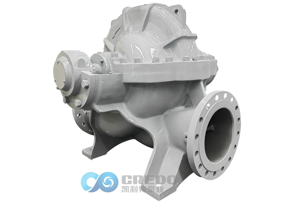
In large-scale water distribution, HVAC, and industrial fluid systems, the split case centrifugal pump is a popular choice due to its high efficiency and reliable flow characteristics. However, even a high-performance pump can become an energy burden if not properly monitored and optimized. By integrating energy monitoring tools, smart sensors, and predictive maintenance strategies, facilities can significantly reduce energy consumption, avoid unexpected failures, and extend the life of their pumping systems.
This article explores how to manage energy consumption of a split case centrifugal pump through real-time monitoring, automation, and data-driven maintenance strategies.
1. Monitor Energy Consumption and Key System Variables
Energy Usage Tracking
A straightforward way to monitor system-wide energy consumption is to install a power meter on the main electrical supply line that feeds the pumping system. This provides a clear overview of energy usage by all components — including the pump motor, control system, and valves.
Benefits of Time-Based Monitoring
Monitoring changes in energy use over time helps identify peak demand periods and idle phases. While this doesn’t directly reduce energy use, it can lower energy costs by avoiding high-demand charges and enabling load balancing through strategic scheduling of pumping operations.
2. Build a Smart Monitoring Strategy
Deploy Critical Sensors
Install sensors and instrumentation at essential points in the system to monitor:
Flow
Pressure
Temperature
Vibration
These sensors serve three primary functions:
Real-time monitoring – Display system parameters and trigger alarms when limits are exceeded.
Automation – Feed data into controllers for automatic system adjustments.
Historical analysis – Build trendlines to assess system performance over time.
3. Enable Real-Time Alerts and Auto-Shutdown Logic
Sensors can be configured with threshold limits to prevent unsafe operation. For example:
A low suction pressure sensor can prevent pump cavitation by sounding an alarm or initiating an automatic shutdown.
High temperature or vibration sensors can protect motors and bearings from damage.
This proactive monitoring not only safeguards equipment but also reduces downtime due to unexpected breakdowns.
4. Automate Operation for Energy Efficiency
Sensors are the foundation of an automated pump control system. For instance:
If the split case centrifugal pump is used for cooling, a temperature sensor can signal a controller to adjust pump speed or modulate a valve, ensuring the pump matches actual system demand.
This intelligent control minimizes unnecessary energy consumption and optimizes system performance in real time.
5. Predictive Maintenance for Long-Term Reliability
From Reactive to Predictive
Instead of waiting for faults to occur or changing components based on fixed schedules, predictive maintenance uses sensor data to anticipate wear or failure. For example:
Differential pressure sensors across filters detect clogging trends.
Vibration sensors installed at pump and motor bearings detect imbalances, misalignment, or bearing wear.
Baseline vs. Real-Time Comparison
After system commissioning, the control system records baseline values (vibration, flow, temperature, pressure). Over time, these values shift. When readings exceed preset tolerances, alarms notify technicians to act before failures occur.
6. Practical Example: Vibration Monitoring
Installing accelerometers on bearing housings of the split case centrifugal pump can:
Capture initial vibration signatures as reference.
Detect increases in vibration amplitude that indicate wear or imbalance.
Trigger alarms or shutdowns when critical limits are reached.
Routine issues like a loose mounting bolt can be corrected easily. After adjustment, real-time sensor feedback confirms whether the fix restored normal operation.
Even in cases of more serious damage, predictive alerts give operators time to plan maintenance without interrupting operations.
7. Beyond Reliability: Energy Optimization
Smart sensors do more than prevent failures. They also reveal opportunities for energy efficiency:
Identifying oversized or underperforming pumps
Diagnosing throttled flow conditions
Revealing system components that need redesign
By applying this strategy to existing systems, facilities can reduce energy consumption, lower operating costs, and increase system uptime — all while getting the most out of their split case centrifugal pump assets.
Conclusion
The split case centrifugal pump is already a highly efficient component in fluid handling systems. But without proper monitoring and intelligent control, even the most reliable pump can become inefficient or prone to failure. By leveraging real-time monitoring, smart automation, and predictive maintenance strategies, organizations can not only optimize energy consumption but also ensure long-term reliability and performance.
Whether you’re retrofitting an old system or fine-tuning a new installation, investing in energy intelligence is the smartest move you can make.
FAQ – for Split Case Pump
Learn about the key spare parts commonly used in split case pumps.
| Split Case Pump Spare Parts & Qty (2 Years) | ||||||||
| For Packing Seal Pump | ||||||||
| Spare Parts/Qty | Pump Qty (Including Spare Pump) | |||||||
| 1 | 2 | 3 | 4 | 5 | 6 | 8 | ≥10 | |
| Shaft Sleeve | 1 | 1 | 1 | 2 | 2 | 3 | 4 | 5 |
| Bearing Collar | 1 | 1 | 1 | 2 | 2 | 3 | 4 | 5 |
| Impeller Collar | 0 | 0 | 0 | 1 | 1 | 1 | 2 | 3 |
| Packing Seal | 1 | 2 | 3 | 4 | 5 | 6 | 8 | 10 |
| O Ring | 1 | 2 | 3 | 4 | 5 | 6 | 8 | 10 |
| Shaft | 0 | 0 | 0 | 1 | 1 | 1 | 2 | 3 |
| Impeller | 0 | 0 | 0 | 1 | 1 | 1 | 2 | 3 |
| Wear Ring | 1 | 1 | 1 | 2 | 2 | 3 | 4 | 5 |
| Packing Ring | 0 | 0 | 0 | 1 | 1 | 1 | 2 | 3 |
| Packing Gland | 0 | 0 | 0 | 1 | 1 | 1 | 2 | 3 |
| Bearing | 1 | 1 | 1 | 2 | 2 | 3 | 4 | 5 |
| For Mechanical Seal Pump | ||||||||
| Spare Parts/Qty | Pump Qty (Including Spare Pump) | |||||||
| 1 | 2 | 3 | 4 | 5 | 6 | 8 | ≥10 | |
| Shaft Sleeve | 1 | 1 | 1 | 2 | 2 | 3 | 4 | 5 |
| Bearing Collar | 1 | 1 | 1 | 2 | 2 | 3 | 4 | 5 |
| Impeller Collar | 0 | 0 | 0 | 1 | 1 | 1 | 2 | 3 |
| Mechanical Seal | 1 | 1 | 1 | 2 | 2 | 3 | 4 | 5 |
| O Ring | 1 | 2 | 3 | 4 | 5 | 6 | 8 | 10 |
| Shaft | 0 | 0 | 0 | 1 | 1 | 1 | 2 | 3 |
| Impeller | 0 | 0 | 0 | 1 | 1 | 1 | 2 | 3 |
| Wear Ring | 1 | 1 | 1 | 2 | 2 | 3 | 4 | 5 |
| Mechanical Gland | 0 | 0 | 0 | 1 | 1 | 1 | 2 | 3 |
| Bearing | 1 | 1 | 1 | 2 | 2 | 3 | 4 | 5 |
Discover how to select the right split case pump materials based on fluid properties and operating conditions.
| Pump Parts | For Clear Water | For Sewage | For Seawater |
| Casing | Cast Iron | Ductile Iron | S.S / Super Dulex |
| Impeller | Cast Iron | Cast Steel | S.S / Super Dulex / Tin Bronze |
| Shaft | Steel | Steel | S.S / Super Dulex |
| Shaft Sleeve | Steel | Steel | S.S / Super Dulex |
| Wear Ring | Cast Iron | Cast Steel | S.S / Super Dulex / Tin Bronze |
| Remark | Final material depends on the liquid condition or the client’s request. | ||
Follow the essential installation steps to ensure safe and reliable operation of the split case pump.
| Standardized Installation Procedure for Split Case Pump | |||
| Work Stage | No. | Main Steps | Key Operations & Notes |
| I. Pre-Installation Preparation | 1 | Site & Foundation Inspection | • Clean the installation site and ensure sufficient space for operation and lifting. • Check the concrete foundation strength, dimensions, elevation, and anchor bolt positions according to drawings. The foundation surface should be flat and free of oil. |
| 2 | Equipment Unpacking & Inspection | • Verify that the pump, motor, and accessories match the contract specifications. • Inspect the equipment for any transportation damage and ensure all parts are complete. • Check that all accompanying documents (drawings, manuals, certificates) are complete. | |
| 3 | Tools & Material Preparation | • Prepare lifting equipment (hoist, sling), shims, level, dial indicator, wrenches, feeler gauge, lubricants, sealant, etc. • Prepare cleaning agents and cloths for cleaning mating surfaces. | |
| II. Pump Body Installation | 4 | Lifting & Positioning | • Lift the pump using the lifting holes or lugs; never lift by the pump shaft or inlet/outlet pipes. • Place the pump on the foundation, insert anchor bolts into base holes, do not tighten yet. |
| 5 | Initial Leveling & Alignment | • Place a level on the pump’s inlet/outlet flange or machined surface, adjust shims to roughly level the pump (tolerance ≤0.1 mm/m). • Use the pump shaft centerline as a reference to preliminarily align the pump. | |
| 6 | Primary Grouting | • Pour high-strength non-shrink grout into the anchor bolt holes; the grout layer should be dense and slightly below the foundation surface. • Curing: wait until the grout is fully cured (usually 3–7 days) before fine adjustment and tightening. | |
| 7 | Final Leveling & Alignment | • After grout curing, tighten anchor bolts. • Recheck pump level with a precision level. • Motor installation & alignment: lift the motor in place, use a dial indicator or laser alignment device, align the motor to ensure pump and motor shafts are coaxial (radial & axial deviation ≤0.05 mm). Tighten motor anchor bolts after alignment. | |
| III. Piping & Accessories Installation | 8 | Piping Connection | • Principle: never force pipe connections using the pump flanges to avoid stress on the pump body. • Piping should be independently supported, ensure natural alignment without stress. • It is recommended to install expansion joints near the pump inlet/outlet to absorb thermal expansion/contraction and installation errors. |
| 9 | Seals & Cooling System | • For mechanical seals, connect flushing/cooling piping, ensure smooth flow, flushing pressure 0.05–0.15 MPa higher than seal chamber. • For packing seals, install packing and adjust gland tightness (do not overtighten initially). | |
| 10 | Lubrication & Instruments | • Add specified grade and quantity of lubricant to bearing housing to oil mark midline. • Install pressure gauge, thermometer, etc.; pressure gauge should be between pump outlet and first valve. | |
| IV. Post-Installation Checks & Test Run | 11 | Final Checks | • Manual rotation: rotate coupling, ensure rotor turns smoothly, no friction or binding. • Check all bolts are tightened and guards are in place. • Jog motor: confirm rotation direction matches pump casing arrow. |
| 12 | Priming & Test Run | • Open inlet valve, fill pump with conveyed medium, completely expel air. • Close outlet valve, start motor. • Slowly open outlet valve to desired condition, check pressure, flow, vibration, noise, bearing temperature (≤80 ℃), and seal leakage. Test run ≥2 hours. | |
Explore proper disassembly and maintenance procedures to maximize the split case pump service life.
| Standardized Disassembly & Maintenance Procedure for Split Case Pump | |||
| Work Stage | No. | Main Steps | Key Operations & Notes |
| I. Pre-Disassembly Preparation | 1 | Shutdown & Isolation | • Safety first: slowly close the outlet valve, cut off power, and apply lockout/tagout (LOTO). • Close the inlet valve, open the pump vent and drain valves, completely drain the medium. For toxic or hazardous media, perform purging and verify safe conditions. |
| 2 | Disconnect External Connections | • Remove coupling guard and connecting bolts. • Disconnect all pipes, instrumentation lines, and cooling/seal water lines if the pump will be lifted as a whole. Seal open ends to prevent foreign object entry. | |
| 3 | Tools & Preparation | • Prepare pullers, hydraulic wrenches, copper bars, lifting equipment, and various wrenches. • Prepare parts boxes and labels to organize and mark removed bolts and small parts for easier reassembly. | |
| II. Pump Body Disassembly | 4 | Remove Accessories | • Remove pressure gauges, thermometers, and other instruments. • Open bearing housing oil drain and collect used lubricant. |
| 5 | Remove Coupling & Bearing End Covers | • Use a puller to smoothly remove the half-coupling from the pump shaft; avoid hammering. • Remove bearing end covers and gland bolts in sequence, then remove the covers. | |
| 6 | Lift Out Rotor Assembly | • Remove bearing housing bolts on both sides of the pump and horizontally lift the entire rotor assembly (shaft, impeller, bearings, sleeves) smoothly. Avoid collisions. | |
| 7 | Disassemble Split Case Pump Body | • Loosen and remove pump casing bolts in a diagonal sequence. • Lift the pump casing carefully and place on a padded or wooden platform. Protect the split case mating surface—avoid dents or scratches. | |
| 8 | Remove Internal Components | • Before disassembly, measure and record key clearances (e.g., impeller to wear ring, bearing clearance). • Use special wrenches to remove impeller locknut, then remove impeller. Remove shaft sleeve, mechanical seal or packing housing sequentially. | |
| III. Inspection, Maintenance & Reassembly | 9 | Parts Cleaning, Inspection & Measurement | • Clean all parts thoroughly, inspect for wear, corrosion, cracks. Focus on: – Impeller: cavitation, wear, dynamic balance. – Wear ring/seal ring: measure wear gap; replace if exceeding limits (typically >1.5× original gap). – Pump shaft: check straightness (total runout ≤0.05 mm). – Bearings: check clearance, rolling surface for pitting or spalling. – Mechanical seals: check stationary/rotating faces and spring elasticity. • Decide whether to repair or replace parts. |
| 10 | Reassembly (Reverse Order of Disassembly) | • Core principle: clean, align, and tighten evenly. • Replace all seals (O-rings, gaskets). Apply a thin layer of sealant (e.g., anaerobic) on split case mating surfaces. • Lift pump casing, tighten bolts diagonally in stages to manufacturer torque. • Reinstall rotor assembly, adjust impeller axial clearance to manufacturer spec. • Install bearings and adjust bearing clearance. • Reinstall coupling and perform precise pump-to-motor alignment (same as installation standard). | |
| 11 | Final Verification | • Manually rotate to ensure smooth, unrestricted motion. • Connect piping, add new lubricant to specified level. • Conduct final verification according to installation procedure “Priming & Test Run” to ensure normal operation parameters. | |
Find practical solutions to the most common split case pump operating issues.
| Split Case Pump Common Faults and Solutions | ||
| Problem | Causes | Solutions |
| 1. Pump not priming / Cannot discharge liquid | 1. Suction pipe, suction valve, foot valve not primed; air ingress. 2. Pump casing or suction pipe contains trapped air. 3. Motor rotation reversed. 4. Suction inlet leakage or failure. 5. Suction lift exceeds allowable maximum. | 1. Prime suction line and foot valve; eliminate air leaks. 2. Vent casing & suction line. 3. Correct motor wiring/rotation. 4. Repair suction inlet. 5. Reduce suction lift or add booster. |
| 2. Flow insufficient / Small discharge | 1. Inlet valve closed or partially closed; suction screen blocked. 2. Impeller blockage, foreign objects. 3. Wear at suction port (seal ring), impeller or casing wear. 4. Suction line contains air. 5. Pump speed too low. | 1. Fully open inlet valve; clean filter/screen. 2. Remove blockage/clean impeller. 3. Repair/replace worn components. 4. Purge air from suction. 5. Restore correct operating speed. |
| 3. Low head / Insufficient pressure | 1. Impeller clearance too large or impeller damage. 2. Low rotation speed. 3. Cavitation. 4. Suction pipe diameter too small. 5. Discharge head exceeds pump capacity. | 1. Adjust or replace impeller. 2. Increase speed within rating. 3. Improve suction conditions or reduce NPSH. 4. Increase suction pipe size. 5. Reduce discharge head. |
| 4. Excessive vibration / Abnormal noise | 1. Shaft misalignment. 2. Bearing damage. 3. Loose motor mounting. 4. Coupling or impeller imbalance. 5. Motor vibration. 6. Base/frame loose. 7. Improper pipe support causing resonance. | 1. Re‑align pump & motor. 2. Replace bearings. 3. Secure motor base. 4. Correct balance; inspect coupling. 5. Reduce motor vibration. 6. Tighten base. 7. Add pipe supports. |
| 5. Bearing overheating | 1. Improper lubrication (insufficient, wrong type, contaminated). 2. Bearing damage. 3. Poor alignment. 4. Bearing housing misfit. 5. Insufficient cooling. 6. Excessive rotational speed. | 1. Re‑lubricate with correct grease/oil. 2. Replace bearings. 3. Realign pump & motor. 4. Adjust housing fit. 5. Improve ventilation/cooling. 6. Operate within speed rating. |
| 6. Mechanical seal leakage | • Seal faces worn, uneven, O‑ring aging, spring failure. • Packing not lubricated or tightened. | • Replace mechanical seal and O‑rings; inspect shaft finish. • Adjust packing gland; ensure correct packing and tension. |
| 7. Motor overload / Tripped protection | 1. Insufficient power supply. 2. Phase loss / Power imbalance / Poor wiring. 3. Excessive load (impeller blockage), pump stalled. 4. Excessive starting current. 5. Motor overheating. 6. Short‑circuit or earth fault. | 1. Restore proper supply voltage. 2. Check wiring and phases; correct imbalance. 3. Remove blockage; clear shaft rotation. 4. Use soft start or reduced voltage starter. 5. Improve cooling. 6. Find & repair electrical fault. |
| 8. Cannot start or slow start | 1. Power supply abnormal (voltage drop). 2. Starter contactor open. 3. Motor winding open circuit. 4. Control circuit faulty. | 1. Check power and restart. 2. Check and replace contactor. 3. Repair/replacement of winding. 4. Correct control wiring. |
| 9. Pump vibration increases at no load | 1. Rotor imbalance, bent shaft. 2. Loose rotating parts. 3. Coupling looseness. 4. Pump suction/delivery line back‑pressure issue. | 1. Balance rotor or repair shaft. 2. Tighten rotating assembly. 3. Tighten coupling. 4. Eliminate back‑pressure and correct piping. |
| 10. Efficiency drop / Performance deterioration | 1. Wear of impeller & casing. 2. Internal passage clogging, scale/slag. 3. Air entrainment in suction. 4. Operating point far from BEP. | 1. Replace worn parts. 2. Clean flow passages; flush. 3. Eliminate suction air leaks. 4. Adjust operating conditions toward BEP. |
Learn the maintenance practices that help improve split case pump reliability and reduce downtime.
| Daily Maintenance and Care for Split Case Pumps | ||
| Maintenance Category | Maintenance Item | Details & Standards |
| I. Pre‑Operation Inspection | 1. Visual & Connection Check | • Check the pump casing, motor, coupling, etc., for cracks, deformation or damage. • Check all connection fasteners (especially pump‑to‑base and base bolts) for tightness to prevent leakage or vibration. • Check piping and joint areas for looseness. |
| 2. Lubrication Inspection | • Oil lubrication: Check if the oil level in the oil chamber is at the center mark; whether the oil is clean. Replace promptly if oil is turbid or contains impurities. • Grease lubrication: Check if the grease is sufficient and clean. Note: Water‑based bearings use grease X; motors use grease Y — the two must not be mixed. | |
| 3. Turn Shaft & Rotation Confirmation | • Manually rotate the coupling to check if the pump shaft rotates freely with no friction noise. • Start motor briefly to confirm the rotation direction is consistent with the direction indicated by the pump arrow. | |
| 4. Seal & Suction Check | • Check the mechanical seal and packing seal condition. • Open pump suction valve and drain water until the casing is full, then vent air (no dry running). | |
| II. Monitoring During Operation | 1. Parameter Monitoring | • Pressure & Flow: Monitor inlet and outlet pressures and flow to ensure operation within the rated range for optimum efficiency. • Bearing Temperature: Bearing temperatures should remain between 40–60 °C, and the motor temperature should not exceed 80 °C. If overheated, check lubrication and cooling systems. |
| 2. Vibration & Noise | • Listen to running noise: should be smooth hum. If there are abnormal noises, impacts, etc., stop and inspect immediately. • Observe vibration condition; abnormal vibration may indicate imbalance, bent shaft, uneven wear, or cavitation. | |
| 3. Seal & Leakage Monitoring | • Mechanical seal: Normal leakage rate should not exceed 5 drops per minute. • Packing seal: Through adjustment tighten, leakage rate should be controlled at about 10‑15 drops/min (approx. 30 ml/min) depending on packing size. Adjust to desired leakage. | |
| 4. Instruments & Motor | • Check all instruments (pressure gauge, temperature gauge, etc.) for normal readings. • Check motor current and electrical system; no abnormal heating. | |
| III. Periodic (Planned) Maintenance | 1. Lubrication Management | • Oil lubrication: Change first after 100 operating hours, then every 500 hours. • Grease lubrication: Generally replenish or change every 3 months; follow manufacturer service schedule. |
| 2. Seal System Maintenance | • Packing seal: Replace packing rings as needed; ensure stuffing box is properly tightened and align packing ring gaps at 90°–120°. • Mechanical seal: Check flushing liquid pressure; it should be 0.05–0.1 MPa. Replace seal if excessive wear or leakage. | |
| 3. Bearing & Coupling Check | • Monthly manually check coupling and shaft for smooth rotation, no abnormal noise. • Periodically check bearing housing for dirt, wear and proper lubrication. | |
| 4. Impeller & Flow Passage Cleaning | • Every 3 months or based on water quality, check impeller for buildup, corrosion, wear; clean off sediment, debris.• Check impeller clearance; if gap is too large (e.g., >0.1 mm), replace as required. | |
| 5. Alignment & Tightening | • Periodically check alignment between pump and motor; allowable deviation ≤0.05 mm. • Retighten base bolts and major fasteners as needed. | |
| IV. Shutdown & Long‑Term Stop | 1. Normal Shutdown | • Procedure: close outlet valve first → power off → close inlet valve and pressure gauge valves. |
| 2. Winter Anti‑Freeze | • When ambient temperature is ≤ 0 °C, after shutdown drain water from pump body, and ensure piping is drained to prevent freezing. | |
| 3. Long‑Term Storage | • Drain all internal water and clean thoroughly. • Apply rust preventive oil (shaft, impeller, contact areas), reinstall and protect for storage. | |
| V. Cleaning & Record Keeping | 1. Equipment Cleaning | • Weekly wipe pump body, motor, and base surfaces; especially clean motor cooling fins. • Regularly clean around instrument panels to prevent dust accumulation. |
| 2. Operation Records | • Establish and maintain operation & maintenance logs including operating hours, pressures, temperature, vibration, lubrication replacement time, fault handling, etc., to facilitate equipment condition tracking and planned maintenance. | |
Related Posts