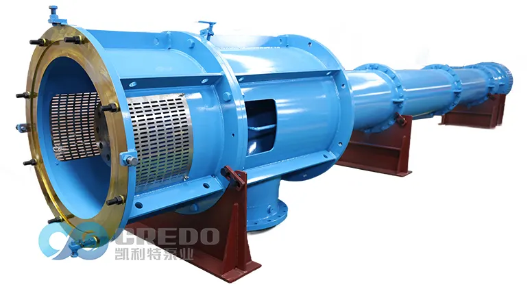
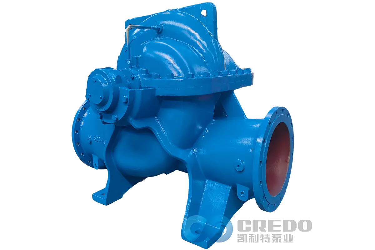
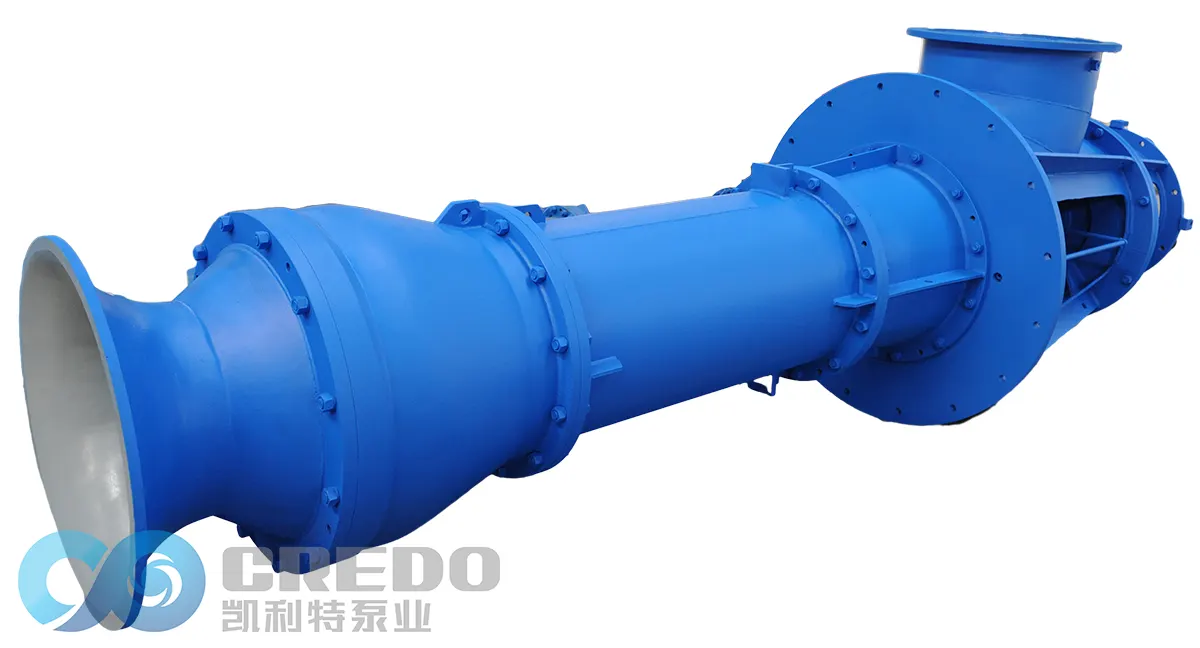
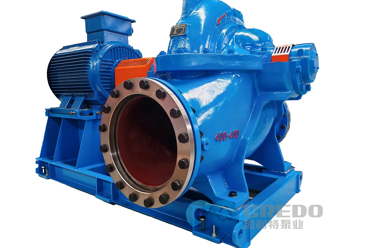
Horizontal Split Case Pump Selection Guide: Impact of Temperature, Viscosity, and Corrosive Properties
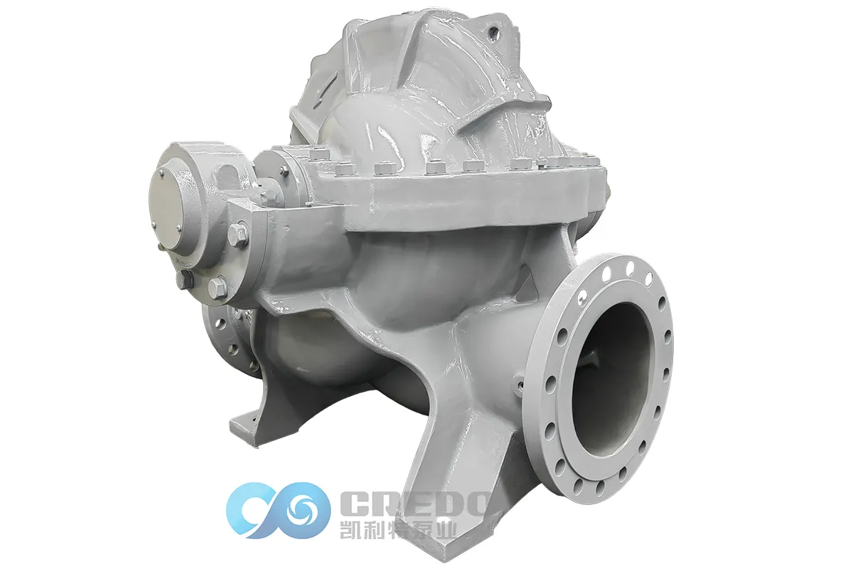
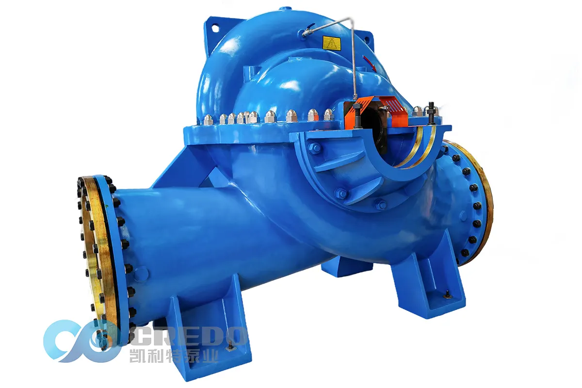
The key principle of accurate horizontal split case pump selection is to match the pump design with the characteristics of the pumped fluid. Liquid temperature, viscosity, and corrosive properties are three critical medium parameters that directly influence pump casing materials, sealing systems, hydraulic design, operating conditions, and overall service life.
During the pump selection process, these three parameters should be carefully evaluated to define the operating limits of the equipment and optimize the pump configuration accordingly. Proper evaluation can effectively prevent common failures such as cavitation, excessive energy consumption, corrosion damage, and motor overload, while significantly reducing lifecycle operation and maintenance costs and ensuring long-term efficient and reliable operation of the pump unit.
This article focuses on these three critical fluid characteristics and systematically analyzes their impact on horizontal split case pump selection, including material selection, structural configuration, performance correction, and application suitability. It provides technical guidance for engineers to achieve accurate and reliable pump selection.
I. Key Considerations for Liquid Temperature Selection
Fluid temperature mainly affects the material resistance, mechanical seal service life, bearing heat dissipation performance, and cavitation characteristics of horizontal split case pumps. Different temperature ranges require specific material selections, sealing solutions, and operating optimization strategies. Therefore, temperature is one of the key factors in determining the suitable design and configuration of a horizontal split case centrifugal pump.
The detailed selection considerations for different temperature conditions are shown in the table below:
| Fluid Temperature Condition | Potential Risks | Recommended Materials | Seal and Bearing Configuration | Cavitation and Operation Optimization Solutions | Typical Applications |
| Normal temperature fluid (0–80℃) | No significant temperature-related risks under normal operating conditions; stable operation | Standard cast iron, conventional cast steel | Standard mechanical seals and conventional lubricating oil/grease | No special optimization required; select the pump according to standard NPSH requirements | Municipal water supply, general industrial circulating water, standard water transfer and drainage systems |
| High temperature fluid (>80℃) | Increased vapor pressure of the fluid, higher risk of internal cavitation; accelerated aging of sealing components; excessive bearing temperature rise; possible thermal deformation or cracking of pump casing | Heat-resistant cast steel, heat-resistant stainless steel; standard cast iron is not recommended | High-temperature mechanical seals; bearing housing with cooling ribs to improve heat dissipation | Strictly verify NPSHA (available NPSH) and NPSHR (required NPSH); reduce pump installation height, increase suction pressure, select larger inlet diameter impellers, install an inducer if required, and carefully adjust speed to balance flow capacity, head, and cavitation resistance | Boiler water circulation, high-temperature process water transfer, industrial heat exchanger circulation systems |
| Low temperature fluid (<0℃) | Risk of brittle fracture of pump components due to low temperature; loss of elasticity of sealing materials causing leakage; increased lubricant viscosity resulting in poor bearing lubrication | Low-temperature impact-resistant cast steel, low-temperature stainless steel | Low-temperature-resistant sealing materials such as fluorosilicone rubber and perfluoroether rubber; low-temperature lubricants | No special cavitation optimization required; focus on material toughness at low temperatures and compatibility between components | Low-temperature process fluid transfer, low-temperature cooling water systems |
II. Key Considerations for Liquid Viscosity Selection
Fluid viscosity directly affects the hydraulic performance, operating efficiency, and energy consumption of horizontal split case pumps. It is also a key parameter for performance correction and motor power selection.
Horizontal split case pumps are centrifugal pumps primarily designed for low-viscosity fluids. As viscosity increases, internal flow resistance rises, resulting in reduced flow capacity, lower head and efficiency, and increased shaft power requirements. Therefore, the applicability of the pump must be carefully evaluated according to different viscosity ranges.
The detailed selection considerations for different viscosity conditions are shown in the table below:
| Fluid Viscosity Range | Potential Operating Impacts | Selection Correction Requirements | Structural Optimization Solutions | Application Suitability |
| Low viscosity (≤5 mm²/s) | Good fluidity, low internal flow resistance, and stable hydraulic performance | No correction required for flow rate, head, or efficiency. Standard clean water performance curves can be directly applied for pump selection | Standard impeller and conventional hydraulic passage design are sufficient | Fully suitable and represents the optimal operating condition for horizontal split case pumps |
| Medium viscosity (5–20 mm²/s) | Reduced fluidity and increased internal flow resistance; slight reduction in flow rate, head, and efficiency; increased shaft power with potential motor overload risk | Performance correction should be carried out according to recognized standards such as Hydraulic Institute (HI) guidelines and applicable industry standards. Motor power margin should be properly increased to avoid overload and failure | Use large-passage impellers and enlarge hydraulic passage areas to reduce flow resistance and improve fluid handling capability | Applicable with proper performance correction and structural optimization |
| High viscosity (>50 mm²/s) | Significant deterioration of hydraulic performance, reduced efficiency, sharply increased energy consumption, and unstable pump operation | Performance correction alone cannot achieve satisfactory operating performance; conventional horizontal split case pump selection is generally not recommended | Standard horizontal split case pump designs cannot effectively adapt to high-viscosity fluids | Generally unsuitable. Positive displacement pumps such as screw pumps or gear pumps are usually preferred for high-viscosity applications |
III. Key Considerations for Liquid Corrosiveness Selection
Fluid corrosive properties are a key factor in selecting the materials of wetted components for horizontal split case pumps. Due to the characteristics of the horizontal split casing design, including additional sealing interfaces and potential assembly gaps, corrosive fluids require careful evaluation of material compatibility, sealing reliability, and long-term operating safety.
Material selection and structural solutions should be accurately matched according to the corrosion level of the pumped fluid. Highly corrosive applications require strict assessment of pump suitability before selection.
The detailed selection considerations for different corrosive conditions are shown in the table below:
| Fluid Corrosion Level | Typical Fluid Applications | Recommended Materials for Wetted Components | Required Supporting Configurations | Application Suitability |
| Non-corrosive fluids | Clean water, condensate water, conventional circulating water | Standard cast iron | Standard sealing components and conventional fasteners | Highly cost-effective and suitable for municipal water supply, general industrial circulating water, and standard water transfer applications |
| Mild corrosion (without chloride ions) | Softened water, low-purity freshwater, mildly corrosive process water | 304 stainless steel | Basic corrosion-resistant seals and stainless steel fasteners | Suitable for long-term stable operation in common mildly corrosive applications |
| Moderate corrosion (low-concentration chlorides, acids, and alkalis) | Low-salinity wastewater, general municipal wastewater, weak acidic or alkaline process fluids | 316L stainless steel | Acid and alkali-resistant mechanical seals and corrosion-resistant fasteners | Applicable in moderate corrosion conditions; caution is required in high chloride environments due to potential pitting corrosion and stress corrosion |
| Severe corrosion (high chloride concentration, concentrated acids/alkalis, strong oxidizing fluids) | Seawater, concentrated acid and alkaline solutions, strong oxidizing process fluids, high-salt wastewater | Standard materials are not recommended; customized 2205/2507 duplex stainless steel or 904L corrosion-resistant alloys may be required | Special anti-corrosion treatment for split casing sealing surfaces, corrosion-resistant mechanical seals, and fully corrosion-resistant fasteners | Not the preferred pump type for severe corrosion applications. Integrated chemical centrifugal pumps are generally recommended. For large-flow applications requiring horizontal split case pumps, customized solutions are possible, but they require strict engineering evaluation and involve significantly higher costs |
Conclusion
During the engineering selection of horizontal split case pumps, flow rate and head provide only basic performance matching. Evaluating fluid temperature, viscosity, and corrosive properties is essential for selecting suitable materials, configurations, and operating parameters to ensure reliable and efficient pump performance.
By accurately matching hydraulic design, sealing systems, and materials with actual operating conditions, horizontal split case pumps can achieve higher reliability, improved energy efficiency, and longer service life, providing dependable solutions for large-flow industrial fluid transfer systems.
FAQ – for Split Case Pump
Learn about the key spare parts commonly used in split case pumps.
| Split Case Pump Spare Parts & Qty (2 Years) | ||||||||
| For Packing Seal Pump | ||||||||
| Spare Parts/Qty | Pump Qty (Including Spare Pump) | |||||||
| 1 | 2 | 3 | 4 | 5 | 6 | 8 | ≥10 | |
| Shaft Sleeve | 1 | 1 | 1 | 2 | 2 | 3 | 4 | 5 |
| Bearing Collar | 1 | 1 | 1 | 2 | 2 | 3 | 4 | 5 |
| Impeller Collar | 0 | 0 | 0 | 1 | 1 | 1 | 2 | 3 |
| Packing Seal | 1 | 2 | 3 | 4 | 5 | 6 | 8 | 10 |
| O Ring | 1 | 2 | 3 | 4 | 5 | 6 | 8 | 10 |
| Shaft | 0 | 0 | 0 | 1 | 1 | 1 | 2 | 3 |
| Impeller | 0 | 0 | 0 | 1 | 1 | 1 | 2 | 3 |
| Wear Ring | 1 | 1 | 1 | 2 | 2 | 3 | 4 | 5 |
| Packing Ring | 0 | 0 | 0 | 1 | 1 | 1 | 2 | 3 |
| Packing Gland | 0 | 0 | 0 | 1 | 1 | 1 | 2 | 3 |
| Bearing | 1 | 1 | 1 | 2 | 2 | 3 | 4 | 5 |
| For Mechanical Seal Pump | ||||||||
| Spare Parts/Qty | Pump Qty (Including Spare Pump) | |||||||
| 1 | 2 | 3 | 4 | 5 | 6 | 8 | ≥10 | |
| Shaft Sleeve | 1 | 1 | 1 | 2 | 2 | 3 | 4 | 5 |
| Bearing Collar | 1 | 1 | 1 | 2 | 2 | 3 | 4 | 5 |
| Impeller Collar | 0 | 0 | 0 | 1 | 1 | 1 | 2 | 3 |
| Mechanical Seal | 1 | 1 | 1 | 2 | 2 | 3 | 4 | 5 |
| O Ring | 1 | 2 | 3 | 4 | 5 | 6 | 8 | 10 |
| Shaft | 0 | 0 | 0 | 1 | 1 | 1 | 2 | 3 |
| Impeller | 0 | 0 | 0 | 1 | 1 | 1 | 2 | 3 |
| Wear Ring | 1 | 1 | 1 | 2 | 2 | 3 | 4 | 5 |
| Mechanical Gland | 0 | 0 | 0 | 1 | 1 | 1 | 2 | 3 |
| Bearing | 1 | 1 | 1 | 2 | 2 | 3 | 4 | 5 |
Discover how to select the right split case pump materials based on fluid properties and operating conditions.
| Pump Parts | For Clear Water | For Sewage | For Seawater |
| Casing | Cast Iron | Ductile Iron | S.S / Super Dulex |
| Impeller | Cast Iron | Cast Steel | S.S / Super Dulex / Tin Bronze |
| Shaft | Steel | Steel | S.S / Super Dulex |
| Shaft Sleeve | Steel | Steel | S.S / Super Dulex |
| Wear Ring | Cast Iron | Cast Steel | S.S / Super Dulex / Tin Bronze |
| Remark | Final material depends on the liquid condition or the client’s request. | ||
Follow the essential installation steps to ensure safe and reliable operation of the split case pump.
| Standardized Installation Procedure for Split Case Pump | |||
| Work Stage | No. | Main Steps | Key Operations & Notes |
| I. Pre-Installation Preparation | 1 | Site & Foundation Inspection | • Clean the installation site and ensure sufficient space for operation and lifting. • Check the concrete foundation strength, dimensions, elevation, and anchor bolt positions according to drawings. The foundation surface should be flat and free of oil. |
| 2 | Equipment Unpacking & Inspection | • Verify that the pump, motor, and accessories match the contract specifications. • Inspect the equipment for any transportation damage and ensure all parts are complete. • Check that all accompanying documents (drawings, manuals, certificates) are complete. | |
| 3 | Tools & Material Preparation | • Prepare lifting equipment (hoist, sling), shims, level, dial indicator, wrenches, feeler gauge, lubricants, sealant, etc. • Prepare cleaning agents and cloths for cleaning mating surfaces. | |
| II. Pump Body Installation | 4 | Lifting & Positioning | • Lift the pump using the lifting holes or lugs; never lift by the pump shaft or inlet/outlet pipes. • Place the pump on the foundation, insert anchor bolts into base holes, do not tighten yet. |
| 5 | Initial Leveling & Alignment | • Place a level on the pump’s inlet/outlet flange or machined surface, adjust shims to roughly level the pump (tolerance ≤0.1 mm/m). • Use the pump shaft centerline as a reference to preliminarily align the pump. | |
| 6 | Primary Grouting | • Pour high-strength non-shrink grout into the anchor bolt holes; the grout layer should be dense and slightly below the foundation surface. • Curing: wait until the grout is fully cured (usually 3–7 days) before fine adjustment and tightening. | |
| 7 | Final Leveling & Alignment | • After grout curing, tighten anchor bolts. • Recheck pump level with a precision level. • Motor installation & alignment: lift the motor in place, use a dial indicator or laser alignment device, align the motor to ensure pump and motor shafts are coaxial (radial & axial deviation ≤0.05 mm). Tighten motor anchor bolts after alignment. | |
| III. Piping & Accessories Installation | 8 | Piping Connection | • Principle: never force pipe connections using the pump flanges to avoid stress on the pump body. • Piping should be independently supported, ensure natural alignment without stress. • It is recommended to install expansion joints near the pump inlet/outlet to absorb thermal expansion/contraction and installation errors. |
| 9 | Seals & Cooling System | • For mechanical seals, connect flushing/cooling piping, ensure smooth flow, flushing pressure 0.05–0.15 MPa higher than seal chamber. • For packing seals, install packing and adjust gland tightness (do not overtighten initially). | |
| 10 | Lubrication & Instruments | • Add specified grade and quantity of lubricant to bearing housing to oil mark midline. • Install pressure gauge, thermometer, etc.; pressure gauge should be between pump outlet and first valve. | |
| IV. Post-Installation Checks & Test Run | 11 | Final Checks | • Manual rotation: rotate coupling, ensure rotor turns smoothly, no friction or binding. • Check all bolts are tightened and guards are in place. • Jog motor: confirm rotation direction matches pump casing arrow. |
| 12 | Priming & Test Run | • Open inlet valve, fill pump with conveyed medium, completely expel air. • Close outlet valve, start motor. • Slowly open outlet valve to desired condition, check pressure, flow, vibration, noise, bearing temperature (≤80 ℃), and seal leakage. Test run ≥2 hours. | |
Explore proper disassembly and maintenance procedures to maximize the split case pump service life.
| Standardized Disassembly & Maintenance Procedure for Split Case Pump | |||
| Work Stage | No. | Main Steps | Key Operations & Notes |
| I. Pre-Disassembly Preparation | 1 | Shutdown & Isolation | • Safety first: slowly close the outlet valve, cut off power, and apply lockout/tagout (LOTO). • Close the inlet valve, open the pump vent and drain valves, completely drain the medium. For toxic or hazardous media, perform purging and verify safe conditions. |
| 2 | Disconnect External Connections | • Remove coupling guard and connecting bolts. • Disconnect all pipes, instrumentation lines, and cooling/seal water lines if the pump will be lifted as a whole. Seal open ends to prevent foreign object entry. | |
| 3 | Tools & Preparation | • Prepare pullers, hydraulic wrenches, copper bars, lifting equipment, and various wrenches. • Prepare parts boxes and labels to organize and mark removed bolts and small parts for easier reassembly. | |
| II. Pump Body Disassembly | 4 | Remove Accessories | • Remove pressure gauges, thermometers, and other instruments. • Open bearing housing oil drain and collect used lubricant. |
| 5 | Remove Coupling & Bearing End Covers | • Use a puller to smoothly remove the half-coupling from the pump shaft; avoid hammering. • Remove bearing end covers and gland bolts in sequence, then remove the covers. | |
| 6 | Lift Out Rotor Assembly | • Remove bearing housing bolts on both sides of the pump and horizontally lift the entire rotor assembly (shaft, impeller, bearings, sleeves) smoothly. Avoid collisions. | |
| 7 | Disassemble Split Case Pump Body | • Loosen and remove pump casing bolts in a diagonal sequence. • Lift the pump casing carefully and place on a padded or wooden platform. Protect the split case mating surface—avoid dents or scratches. | |
| 8 | Remove Internal Components | • Before disassembly, measure and record key clearances (e.g., impeller to wear ring, bearing clearance). • Use special wrenches to remove impeller locknut, then remove impeller. Remove shaft sleeve, mechanical seal or packing housing sequentially. | |
| III. Inspection, Maintenance & Reassembly | 9 | Parts Cleaning, Inspection & Measurement | • Clean all parts thoroughly, inspect for wear, corrosion, cracks. Focus on: – Impeller: cavitation, wear, dynamic balance. – Wear ring/seal ring: measure wear gap; replace if exceeding limits (typically >1.5× original gap). – Pump shaft: check straightness (total runout ≤0.05 mm). – Bearings: check clearance, rolling surface for pitting or spalling. – Mechanical seals: check stationary/rotating faces and spring elasticity. • Decide whether to repair or replace parts. |
| 10 | Reassembly (Reverse Order of Disassembly) | • Core principle: clean, align, and tighten evenly. • Replace all seals (O-rings, gaskets). Apply a thin layer of sealant (e.g., anaerobic) on split case mating surfaces. • Lift pump casing, tighten bolts diagonally in stages to manufacturer torque. • Reinstall rotor assembly, adjust impeller axial clearance to manufacturer spec. • Install bearings and adjust bearing clearance. • Reinstall coupling and perform precise pump-to-motor alignment (same as installation standard). | |
| 11 | Final Verification | • Manually rotate to ensure smooth, unrestricted motion. • Connect piping, add new lubricant to specified level. • Conduct final verification according to installation procedure “Priming & Test Run” to ensure normal operation parameters. | |
Find practical solutions to the most common split case pump operating issues.
| Split Case Pump Common Faults and Solutions | ||
| Problem | Causes | Solutions |
| 1. Pump not priming / Cannot discharge liquid | 1. Suction pipe, suction valve, foot valve not primed; air ingress. 2. Pump casing or suction pipe contains trapped air. 3. Motor rotation reversed. 4. Suction inlet leakage or failure. 5. Suction lift exceeds allowable maximum. | 1. Prime suction line and foot valve; eliminate air leaks. 2. Vent casing & suction line. 3. Correct motor wiring/rotation. 4. Repair suction inlet. 5. Reduce suction lift or add booster. |
| 2. Flow insufficient / Small discharge | 1. Inlet valve closed or partially closed; suction screen blocked. 2. Impeller blockage, foreign objects. 3. Wear at suction port (seal ring), impeller or casing wear. 4. Suction line contains air. 5. Pump speed too low. | 1. Fully open inlet valve; clean filter/screen. 2. Remove blockage/clean impeller. 3. Repair/replace worn components. 4. Purge air from suction. 5. Restore correct operating speed. |
| 3. Low head / Insufficient pressure | 1. Impeller clearance too large or impeller damage. 2. Low rotation speed. 3. Cavitation. 4. Suction pipe diameter too small. 5. Discharge head exceeds pump capacity. | 1. Adjust or replace impeller. 2. Increase speed within rating. 3. Improve suction conditions or reduce NPSH. 4. Increase suction pipe size. 5. Reduce discharge head. |
| 4. Excessive vibration / Abnormal noise | 1. Shaft misalignment. 2. Bearing damage. 3. Loose motor mounting. 4. Coupling or impeller imbalance. 5. Motor vibration. 6. Base/frame loose. 7. Improper pipe support causing resonance. | 1. Re‑align pump & motor. 2. Replace bearings. 3. Secure motor base. 4. Correct balance; inspect coupling. 5. Reduce motor vibration. 6. Tighten base. 7. Add pipe supports. |
| 5. Bearing overheating | 1. Improper lubrication (insufficient, wrong type, contaminated). 2. Bearing damage. 3. Poor alignment. 4. Bearing housing misfit. 5. Insufficient cooling. 6. Excessive rotational speed. | 1. Re‑lubricate with correct grease/oil. 2. Replace bearings. 3. Realign pump & motor. 4. Adjust housing fit. 5. Improve ventilation/cooling. 6. Operate within speed rating. |
| 6. Mechanical seal leakage | • Seal faces worn, uneven, O‑ring aging, spring failure. • Packing not lubricated or tightened. | • Replace mechanical seal and O‑rings; inspect shaft finish. • Adjust packing gland; ensure correct packing and tension. |
| 7. Motor overload / Tripped protection | 1. Insufficient power supply. 2. Phase loss / Power imbalance / Poor wiring. 3. Excessive load (impeller blockage), pump stalled. 4. Excessive starting current. 5. Motor overheating. 6. Short‑circuit or earth fault. | 1. Restore proper supply voltage. 2. Check wiring and phases; correct imbalance. 3. Remove blockage; clear shaft rotation. 4. Use soft start or reduced voltage starter. 5. Improve cooling. 6. Find & repair electrical fault. |
| 8. Cannot start or slow start | 1. Power supply abnormal (voltage drop). 2. Starter contactor open. 3. Motor winding open circuit. 4. Control circuit faulty. | 1. Check power and restart. 2. Check and replace contactor. 3. Repair/replacement of winding. 4. Correct control wiring. |
| 9. Pump vibration increases at no load | 1. Rotor imbalance, bent shaft. 2. Loose rotating parts. 3. Coupling looseness. 4. Pump suction/delivery line back‑pressure issue. | 1. Balance rotor or repair shaft. 2. Tighten rotating assembly. 3. Tighten coupling. 4. Eliminate back‑pressure and correct piping. |
| 10. Efficiency drop / Performance deterioration | 1. Wear of impeller & casing. 2. Internal passage clogging, scale/slag. 3. Air entrainment in suction. 4. Operating point far from BEP. | 1. Replace worn parts. 2. Clean flow passages; flush. 3. Eliminate suction air leaks. 4. Adjust operating conditions toward BEP. |
Learn the maintenance practices that help improve split case pump reliability and reduce downtime.
| Daily Maintenance and Care for Split Case Pumps | ||
| Maintenance Category | Maintenance Item | Details & Standards |
| I. Pre‑Operation Inspection | 1. Visual & Connection Check | • Check the pump casing, motor, coupling, etc., for cracks, deformation or damage. • Check all connection fasteners (especially pump‑to‑base and base bolts) for tightness to prevent leakage or vibration. • Check piping and joint areas for looseness. |
| 2. Lubrication Inspection | • Oil lubrication: Check if the oil level in the oil chamber is at the center mark; whether the oil is clean. Replace promptly if oil is turbid or contains impurities. • Grease lubrication: Check if the grease is sufficient and clean. Note: Water‑based bearings use grease X; motors use grease Y — the two must not be mixed. | |
| 3. Turn Shaft & Rotation Confirmation | • Manually rotate the coupling to check if the pump shaft rotates freely with no friction noise. • Start motor briefly to confirm the rotation direction is consistent with the direction indicated by the pump arrow. | |
| 4. Seal & Suction Check | • Check the mechanical seal and packing seal condition. • Open pump suction valve and drain water until the casing is full, then vent air (no dry running). | |
| II. Monitoring During Operation | 1. Parameter Monitoring | • Pressure & Flow: Monitor inlet and outlet pressures and flow to ensure operation within the rated range for optimum efficiency. • Bearing Temperature: Bearing temperatures should remain between 40–60 °C, and the motor temperature should not exceed 80 °C. If overheated, check lubrication and cooling systems. |
| 2. Vibration & Noise | • Listen to running noise: should be smooth hum. If there are abnormal noises, impacts, etc., stop and inspect immediately. • Observe vibration condition; abnormal vibration may indicate imbalance, bent shaft, uneven wear, or cavitation. | |
| 3. Seal & Leakage Monitoring | • Mechanical seal: Normal leakage rate should not exceed 5 drops per minute. • Packing seal: Through adjustment tighten, leakage rate should be controlled at about 10‑15 drops/min (approx. 30 ml/min) depending on packing size. Adjust to desired leakage. | |
| 4. Instruments & Motor | • Check all instruments (pressure gauge, temperature gauge, etc.) for normal readings. • Check motor current and electrical system; no abnormal heating. | |
| III. Periodic (Planned) Maintenance | 1. Lubrication Management | • Oil lubrication: Change first after 100 operating hours, then every 500 hours. • Grease lubrication: Generally replenish or change every 3 months; follow manufacturer service schedule. |
| 2. Seal System Maintenance | • Packing seal: Replace packing rings as needed; ensure stuffing box is properly tightened and align packing ring gaps at 90°–120°. • Mechanical seal: Check flushing liquid pressure; it should be 0.05–0.1 MPa. Replace seal if excessive wear or leakage. | |
| 3. Bearing & Coupling Check | • Monthly manually check coupling and shaft for smooth rotation, no abnormal noise. • Periodically check bearing housing for dirt, wear and proper lubrication. | |
| 4. Impeller & Flow Passage Cleaning | • Every 3 months or based on water quality, check impeller for buildup, corrosion, wear; clean off sediment, debris.• Check impeller clearance; if gap is too large (e.g., >0.1 mm), replace as required. | |
| 5. Alignment & Tightening | • Periodically check alignment between pump and motor; allowable deviation ≤0.05 mm. • Retighten base bolts and major fasteners as needed. | |
| IV. Shutdown & Long‑Term Stop | 1. Normal Shutdown | • Procedure: close outlet valve first → power off → close inlet valve and pressure gauge valves. |
| 2. Winter Anti‑Freeze | • When ambient temperature is ≤ 0 °C, after shutdown drain water from pump body, and ensure piping is drained to prevent freezing. | |
| 3. Long‑Term Storage | • Drain all internal water and clean thoroughly. • Apply rust preventive oil (shaft, impeller, contact areas), reinstall and protect for storage. | |
| V. Cleaning & Record Keeping | 1. Equipment Cleaning | • Weekly wipe pump body, motor, and base surfaces; especially clean motor cooling fins. • Regularly clean around instrument panels to prevent dust accumulation. |
| 2. Operation Records | • Establish and maintain operation & maintenance logs including operating hours, pressures, temperature, vibration, lubrication replacement time, fault handling, etc., to facilitate equipment condition tracking and planned maintenance. | |
Related Posts